
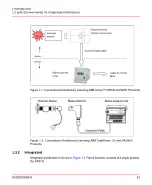
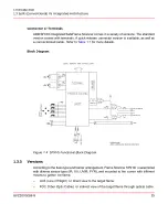


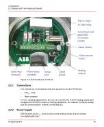


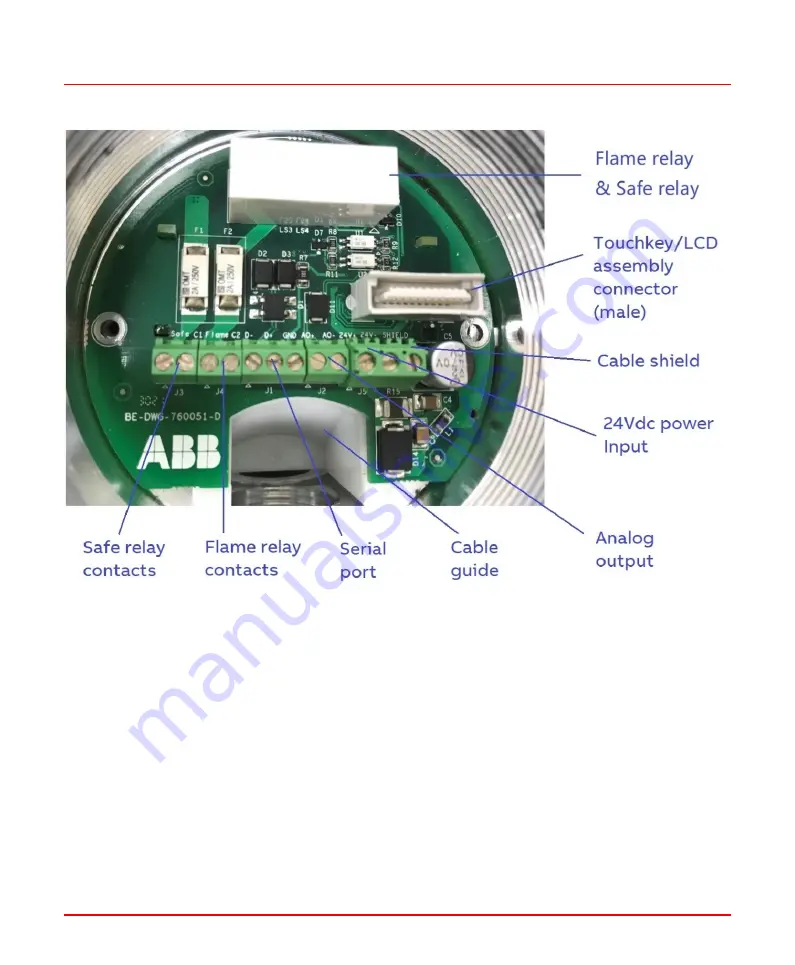
Figure 2.5: Terminal Board of SF910i
2.2.1
Connections
The minimal set of connections that are required to use the SF910i are:
–
24V
DC
power
–
Relay contacts
In more complete applications, the user can connect the 4-20mA analog output (and
configure the SF910i to output an internal variable as, for instance, the flame quality)
and the communication network (one MODBUS).
2.2.2
Power Supply
SF910i works at 24V
DC
. It has inrush current limiting circuits and an internal
non-replaceable fuse.
8VZZ005286 B
34
2 Hardware
2.2 Display and Terminations Boards
Содержание Uvisor SF910i
Страница 1: ...Combustion Instrumentation User Manual Uvisor SF910i Integrated SafeFlame Scanner PROCESS AUTOMATION...
Страница 2: ......
Страница 6: ......
Страница 20: ...8VZZ005286 B 20...
Страница 30: ...8VZZ005286 B 30...
Страница 67: ...Figure 7 5 Version Display in Normal Mode 8VZZ005286 B 67 7 Operating Display 7 5 Version Display...
Страница 68: ...8VZZ005286 B 68...
Страница 78: ...8VZZ005286 B 78...
Страница 90: ...8VZZ005286 B 90...
Страница 92: ...8VZZ005286 B 92...
Страница 97: ...Figure 14 2 Flame Temperature Parameters Screen 8VZZ005286 B 97 14 Flame Temperature Measurement...
Страница 98: ...8VZZ005286 B 98...
Страница 108: ...8VZZ005286 B 108...
Страница 114: ...8VZZ005286 B 114...
Страница 118: ...8VZZ005286 B 118...
Страница 125: ...8 Fit in place the SF910i Flame Scanner 8VZZ005286 B 125 19 Repair and Replacement 19 2 Fiber Optic Replacement...
Страница 126: ...8VZZ005286 B 126...
Страница 128: ...8VZZ005286 B 128...
Страница 130: ...8VZZ005286 B 130...
Страница 150: ...8VZZ005286 B 150...
Страница 151: ...Appendix E Drawings 8VZZ005286 B 151 E Drawings...
Страница 152: ...Figure E 1 Enclosure Quick Release Connector and Version LOS 8VZZ005286 B 152 E Drawings...
Страница 153: ...Figure E 2 Enclosure NPT Cable Inlet and Version LOS 8VZZ005286 B 153 E Drawings...
Страница 154: ...Figure E 3 Enclosure Quick Release Connector and Version FOC 8VZZ005286 B 154 E Drawings...
Страница 155: ...Figure E 4 Enclosure NPT Cable Inlet and Version FOC 8VZZ005286 B 155 E Drawings...
Страница 156: ...Figure E 5 FOC Flexible Assembly 8VZZ005286 B 156 E Drawings...
Страница 157: ...Figure E 6 FOC Rigid Assembly 8VZZ005286 B 157 E Drawings...
Страница 160: ...Figure E 9 Bailey Flame ON Standard Replacement 8VZZ005286 B 160 E Drawings...
Страница 161: ...Figure E 10 Typical Bailey Flame ON Installation 8VZZ005286 B 161 E Drawings...
Страница 162: ...8VZZ005286 B 162...
Страница 164: ...F 1 Earth Connection Cable Figure F 1 Earth Connections 8VZZ005286 B 164 F Cables F 1 Earth Connection Cable...
Страница 170: ...8VZZ005286 B 170...
Страница 172: ...Figure G 1 Diaphragm for SF910i FOC Scanner 8VZZ005286 B 172 G Fittings G 1 TU_KIT03 Set of Diaphragms for SF910i FOC...
Страница 178: ...G 7 Counter Flange 8VZZ005286 B 178 G Fittings G 7 Counter Flange...
Страница 179: ...Figure G 7 Boiler Mounting Counter Flange for FOC Installation 8VZZ005286 B 179 G Fittings G 7 Counter Flange...
Страница 189: ......