


21
Cyber Security Deployment
Cyber security measures need be taken to protect the reliability, integrity, and availability
of power and automation technologies against unauthorized access or attack. ABB
recognizes the importance of cyber security in control-based products/systems and
solutions for infrastructure and industry, and is working closely with the customers to
address the new challenges.
Below measures are strongly suggested:
–
On physical access
: The device local configuration can only be done manually by
workers near the device and through touch key buttons, where the products are
located near the burners, where is physically protected area in customer site
(including commissioning, configuration, maintenance phase, and so on), and only
authorized workers can access it, which is the trust boundary.
–
On interacting with the products
: The touch key buttons could only be operated
by human finger with certain keying speed using specific buttons-combination that
are accepted to avoid wrongly pressing, and specific configuration value rules are
applied to avoid wrong value setting.
–
On ATB/CPU board
: Not open/disassemble the ATB + CPU + SE board. Do not
touch or operate the CPU programming interfaces in the CPU board located inside
the enclosure/beneath the ATB (termination board) PCBA, which are sealed and
not allowed customer to access through warranty paper (anti-tear sticker). Otherwise,
the warranty is also lost.
–
On Modbus communication
: Secure the Modbus RS485 communiation lines are
not attacked/destroyed/interfered/traced/spoofed by outsiders, for example, through
physics restriction on related wiring/looping area. And plant management engineers
shall strictly manage the MODBUS/RTU network and ensure that all other devices
connected to the network are fully trusted.
–
On Modbus host
: As stated in
SF910i Flame Explorer User Manual (8VZZ005308)
.
8VZZ005286 B
129
21 Cyber Security Deployment
Содержание Uvisor SF910i
Страница 1: ...Combustion Instrumentation User Manual Uvisor SF910i Integrated SafeFlame Scanner PROCESS AUTOMATION...
Страница 2: ......
Страница 6: ......
Страница 20: ...8VZZ005286 B 20...
Страница 30: ...8VZZ005286 B 30...
Страница 67: ...Figure 7 5 Version Display in Normal Mode 8VZZ005286 B 67 7 Operating Display 7 5 Version Display...
Страница 68: ...8VZZ005286 B 68...
Страница 78: ...8VZZ005286 B 78...
Страница 90: ...8VZZ005286 B 90...
Страница 92: ...8VZZ005286 B 92...
Страница 97: ...Figure 14 2 Flame Temperature Parameters Screen 8VZZ005286 B 97 14 Flame Temperature Measurement...
Страница 98: ...8VZZ005286 B 98...
Страница 108: ...8VZZ005286 B 108...
Страница 114: ...8VZZ005286 B 114...
Страница 118: ...8VZZ005286 B 118...
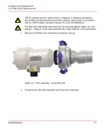
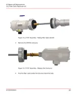
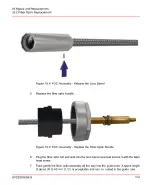
Страница 125: ...8 Fit in place the SF910i Flame Scanner 8VZZ005286 B 125 19 Repair and Replacement 19 2 Fiber Optic Replacement...
Страница 126: ...8VZZ005286 B 126...
Страница 128: ...8VZZ005286 B 128...
Страница 130: ...8VZZ005286 B 130...
Страница 150: ...8VZZ005286 B 150...
Страница 151: ...Appendix E Drawings 8VZZ005286 B 151 E Drawings...
Страница 152: ...Figure E 1 Enclosure Quick Release Connector and Version LOS 8VZZ005286 B 152 E Drawings...
Страница 153: ...Figure E 2 Enclosure NPT Cable Inlet and Version LOS 8VZZ005286 B 153 E Drawings...
Страница 154: ...Figure E 3 Enclosure Quick Release Connector and Version FOC 8VZZ005286 B 154 E Drawings...
Страница 155: ...Figure E 4 Enclosure NPT Cable Inlet and Version FOC 8VZZ005286 B 155 E Drawings...
Страница 156: ...Figure E 5 FOC Flexible Assembly 8VZZ005286 B 156 E Drawings...
Страница 157: ...Figure E 6 FOC Rigid Assembly 8VZZ005286 B 157 E Drawings...
Страница 160: ...Figure E 9 Bailey Flame ON Standard Replacement 8VZZ005286 B 160 E Drawings...
Страница 161: ...Figure E 10 Typical Bailey Flame ON Installation 8VZZ005286 B 161 E Drawings...
Страница 162: ...8VZZ005286 B 162...
Страница 164: ...F 1 Earth Connection Cable Figure F 1 Earth Connections 8VZZ005286 B 164 F Cables F 1 Earth Connection Cable...
Страница 170: ...8VZZ005286 B 170...
Страница 172: ...Figure G 1 Diaphragm for SF910i FOC Scanner 8VZZ005286 B 172 G Fittings G 1 TU_KIT03 Set of Diaphragms for SF910i FOC...
Страница 178: ...G 7 Counter Flange 8VZZ005286 B 178 G Fittings G 7 Counter Flange...
Страница 179: ...Figure G 7 Boiler Mounting Counter Flange for FOC Installation 8VZZ005286 B 179 G Fittings G 7 Counter Flange...
Страница 189: ......