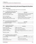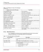
Table 17.5: Hardware Circuitry Error Messages
(Continued)
Description
Hardware Circuitry Error Messages
Over temperature
OVERTEMPERATURE
Flame-relay 1 driving failure
FLAME RELAY FAILURE
Flame-relay 2 driving failure
SAFE RELAY FAILURE
The input signal of both sensors are higher than 2.45V
SENSORS VALUES TOO HIGH
Sensor type unknown
SENSOR TYPE UNKNOWN
Check internal sensor short fault
SENSOR SHORT FAILURE
Input signal too high
INPUT SIGNAL TOO HIGH
EEPROM is no longer responding to read/write requests
FRAM DEADLOCK
Analog input wrong conversion
A/D CONVERSION FAILURE
2.5V reference voltage failure
REFERENCE VOLTAGE FAILURE
0V reference voltage failure
ZERO VOLTAGE FAILURE
Sensor 1 voltage fail
CHANNEL 1 VOLTAGE FAILURE
Sensor 2 voltage fail
CHANNEL 2 VOLTAGE FAILURE
Wrong frequency: there is a discrepancy between the
CPU oscillator
CLOCK TEST FAILURE
17.1.2 Non-Fatal Errors
Error messages for non-fatal errors are reported through the serial communication
channels, and stored in the Fault History field of the local display.
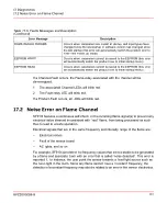
Table 17.6: Faults Messages and Description
Description
Error Message
Low-voltage input and low Flicker-Frequency (less than 5 Hz) [Safe Flame
only]
NO INPUT SIGNAL
High voltage limit reached [Safe Flame, 4 to 20 ma]
HIGH INPUT LIMIT
Low intensity and high Flicker-Frequency error, based on the three
following conditions:
FREQUENCY HIGH
–
If Intensity Drop-Out is > 3 AND
–
Current Intensity is <= 3 AND
–
Frequency > 98
8VZZ005286 B
111
17 Diagnostics
17.1 Failures Detected by On-board Diagnostic Routines
Содержание Uvisor SF910i
Страница 1: ...Combustion Instrumentation User Manual Uvisor SF910i Integrated SafeFlame Scanner PROCESS AUTOMATION...
Страница 2: ......
Страница 6: ......
Страница 20: ...8VZZ005286 B 20...
Страница 30: ...8VZZ005286 B 30...
Страница 67: ...Figure 7 5 Version Display in Normal Mode 8VZZ005286 B 67 7 Operating Display 7 5 Version Display...
Страница 68: ...8VZZ005286 B 68...
Страница 78: ...8VZZ005286 B 78...
Страница 90: ...8VZZ005286 B 90...
Страница 92: ...8VZZ005286 B 92...
Страница 97: ...Figure 14 2 Flame Temperature Parameters Screen 8VZZ005286 B 97 14 Flame Temperature Measurement...
Страница 98: ...8VZZ005286 B 98...
Страница 108: ...8VZZ005286 B 108...
Страница 114: ...8VZZ005286 B 114...
Страница 118: ...8VZZ005286 B 118...
Страница 125: ...8 Fit in place the SF910i Flame Scanner 8VZZ005286 B 125 19 Repair and Replacement 19 2 Fiber Optic Replacement...
Страница 126: ...8VZZ005286 B 126...
Страница 128: ...8VZZ005286 B 128...
Страница 130: ...8VZZ005286 B 130...
Страница 150: ...8VZZ005286 B 150...
Страница 151: ...Appendix E Drawings 8VZZ005286 B 151 E Drawings...
Страница 152: ...Figure E 1 Enclosure Quick Release Connector and Version LOS 8VZZ005286 B 152 E Drawings...
Страница 153: ...Figure E 2 Enclosure NPT Cable Inlet and Version LOS 8VZZ005286 B 153 E Drawings...
Страница 154: ...Figure E 3 Enclosure Quick Release Connector and Version FOC 8VZZ005286 B 154 E Drawings...
Страница 155: ...Figure E 4 Enclosure NPT Cable Inlet and Version FOC 8VZZ005286 B 155 E Drawings...
Страница 156: ...Figure E 5 FOC Flexible Assembly 8VZZ005286 B 156 E Drawings...
Страница 157: ...Figure E 6 FOC Rigid Assembly 8VZZ005286 B 157 E Drawings...
Страница 160: ...Figure E 9 Bailey Flame ON Standard Replacement 8VZZ005286 B 160 E Drawings...
Страница 161: ...Figure E 10 Typical Bailey Flame ON Installation 8VZZ005286 B 161 E Drawings...
Страница 162: ...8VZZ005286 B 162...
Страница 164: ...F 1 Earth Connection Cable Figure F 1 Earth Connections 8VZZ005286 B 164 F Cables F 1 Earth Connection Cable...
Страница 170: ...8VZZ005286 B 170...
Страница 172: ...Figure G 1 Diaphragm for SF910i FOC Scanner 8VZZ005286 B 172 G Fittings G 1 TU_KIT03 Set of Diaphragms for SF910i FOC...
Страница 178: ...G 7 Counter Flange 8VZZ005286 B 178 G Fittings G 7 Counter Flange...
Страница 179: ...Figure G 7 Boiler Mounting Counter Flange for FOC Installation 8VZZ005286 B 179 G Fittings G 7 Counter Flange...
Страница 189: ......

