background image

- 40 -

UMC22-FBP

Universal Motor Controller UMC22-FBP 
Software version 4.0

FieldBusPlug / Issue: 02.2008

V 6

Chapter 4.2.2~1

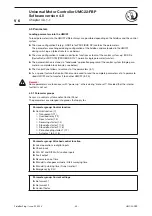
4.2.2 Monitoring data - Details

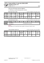
Digital monitorings

Byte

Bit

Short description

Status

Description

0

0

RUN REVERSE

1

Motor running reverse 

and 

check-back (current/aux. contact) = 1

1

OFF

0

RUN command is active 

or 

current is still fl owing after off command

1

Motor stopped 

and 

no current is fl owing 

and 

no RUN command is active

2

RUN FORWARD

1

Motor running forward 

and 

check-back (current/aux. contact) = 1

3

-

-

4

REVERSE
LOCK-OUT TIME 

2)

0

Reverse lock-out time is not running.

1

Reverse lock-out time running. Starts with OFF 
command. The command of the opposite direction is 
accepted only when Reverse lock-out time is over.

5

LOCAL CONTROL

0

Local control is not active.

1

Local control via Control Panel or digital inputs is 
activated. RUN commands of the control system are 
ignored.

Details see chapter 4.3.4

6

FAULT

0

No fault exists

1

Any Fault condition exists: Overload, no check-back 
when started, etc. 
Details see Diagnosis telegram, Fault Bytes 0 and 1.
Fault must be acknowledged via fi eldbus command 
FAULT RESET or with Control Panel.

7

WARNING

0

No warning exists

1

Any warning exists. 
Details see Diagnosis telegram, Warning Byte 2 and 3.

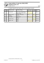
1

0

UMC22 input DI5

-

Reads UMC22 digital inputs DI0 ...DI5, 
independent of the parameterizing

1

UMC22 input DI4

-

2

UMC22 input DI3

-

3

UMC22 input DI2

-

4

UMC22 input DI1

-

5

UMC22 input DI0

-

6

-

-

-

7

-

-

-

Analog monitorings

0

0-7

Motor current in % 
of set current

-

Byte low

1

0-7

-

Byte high

1)

 Only for reversing starter!

Содержание UMC22-FBP

Страница 1: ...2 11 10 DI DI DI DI DI DI 24 24 0 5 4 3 2 1 0 V V V EXT T1 8 DO 1 7 DO 0 6 DO C 5 DO C 9 DO 2 8 7 6 5 9 T2 3 4 UMC22 READY MOT ON FAULT 2CDC 342 007 F0007 Technical Description V6 Universal Motor Controller UMC22 FBP Software version 4 0 ...

Страница 2: ... the features 6 1 3 Construction 6 1 4 Overload protection 7 1 5 Other features 7 1 6 New features in comparison to preceeding versions 8 1 6 1 Version 3 0 3 10 8 1 6 2 Version 3 10 3 30 8 1 6 3 Version 3 30 3 31 8 1 6 4 Version 3 31 3 4 9 1 6 5 Version 3 4 4 0 9 1 7 Compatibility 10 Universal Motor Controller For high grade motor protection and control current range 0 24 to 63 A up to 850 A with ...

Страница 3: ...ieldbus slave 23 3 4 Switch on and off motor 24 3 4 1 Regular start and stop 24 3 4 2 Stop via multi function inputs 26 3 4 3 Emergency start 27 3 4 4 Tip function 28 3 5 Earth fault 29 3 6 Motor protection with thermistor PTC acc to EN 60947 8 type A sensors 31 3 7 Signalling 32 3 7 1 Infos available on the LEDs 32 3 7 2 Control Panel Info and Password panel control 33 3 7 3 Control Panel Direct ...

Страница 4: ...sparent 78 7 2 Overload relay 81 7 3 Direct starter 85 7 4 Reversing starter 92 7 5 Star delta starter 1 100 7 6 Star delta starter 2 108 7 7 Pole changing starter 1 116 7 8 Actuator 1 2 3 and 4 126 8 Control Panel Overview and menu 134 8 1 Overview Control Panel ACS100 PAN 135 8 1 1 Menu levels 135 8 1 2 Buttons on the Control Panel 136 8 1 3 Direct panel control 137 8 1 3 1 Current indication in...

Страница 5: ... is shown in chapter 3 4 2 Find out which steps during planning and commissioning are necessary Chapter 3 1 ff also gives more detailed hints e g chapter 3 2 1 chapter 3 2 2 chapter 3 2 4 etc The way to integrate the UMC22 into the different types of control systems DCS is unfortunately not uniform Chapter 3 3 3 gives hints based on the AC31 CPU 07KT98 that can help to understand The integration i...

Страница 6: ... parameterized as earth fault input 3 5 Via a PTC input the UMC22 can be connected to PTC sensors 3 6 The status of the digital inputs detailed diagnosis information and the parameters are accessible via the fieldbus supposed the fieldbus offers the appropiate features 4 2 1 LEDs on the UMC22 monitor Ready Motor On or Fault 3 7 1 Additional the Control Panel ACS100 PAN separate delivery offers sim...

Страница 7: ...ith parameter 4 3 4 Phase loss protection 4 3 4 Short circuit protection of the motor lines by external fuses or circuit breakers on the line side Blocking protection configurable Warn limits for lower and upper current threshold adjustable 1 5 Other features With parameter Bus fault reaction it can be selected between Relays off or Outputs retain status in case of automation system or fieldbus fa...

Страница 8: ...oduction process it is used for Via the parameters DI0 Multi function input DI1 Multi function input and DI2 Multi function input the inputs DI0 DI1 and DI2 can be parameterized as Multi function inputs Remark Multi function input DI2 replaces keeping the compatibility the former parameter Fault input DI2 Control Panel functions and handling The Control Panel offers the simplified operation Direct...

Страница 9: ...unction Fault output with flashing function The fault output can be set into flashing mode with parameter 24 Fault output 4 3 4 Advanced diagnosis functions External faults at the digital inputs DI0 DI1 and DI2 can be differentiated via fieldbus diagnosis Byte 3 Bits 4 6 via Control Panel fault number F022 F023 and F024 1 6 5 Version 3 4 4 0 Jogging inching mode for digital inputs except operation...

Страница 10: ...ace the older Versions V3 0 and V3 10 with one exception If the parameter Check back Auxiliary contacts is selected the UMC22 sets the internal fault signal when power up Reason In older configuration files GSD EDS the former spare parameter no 5 is set to 1 In the new UMC22 V3 30 this means that the DI0 Multi function shall operate as Fault input This represents a conflict that leads to the fault...

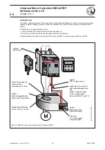
Страница 11: ...ruction of the UMC22 FBP Fig 2 2 UMC22 FBP with external current transformer for higher currents Chapter 2 1 1 4 UMC22 FBP current transformer unit UMC22 FBP controller unit Label ACS100 PAN Control Panel optional FieldBusPlug optional Complete device with mounted accessories 2CDC 342 034 F0206 2CDC 342 035 F0206 max lenght 2 m each wire size 2 5 mm2 ...

Страница 12: ...sPlug DIN rail Front label e g for slave address Control Panel holder Insert the Control Panel at this holder then snap it into the pawl on the upper side The electrical contacts are automatically connected Connecting terminals for the digital inputs Connecting terminals for the external supply voltage supply for internal electronics Current path for measuring the motor current Snap mountable Cont...

Страница 13: ...the wiring of the motor to fix the correct Set current for perfect motor protection Example For 冑3 inner delta wiring the parameter Current factor can be changed to 1 73 to get displayed the real Set currents on the Control Panel and in the control system External current transformer for higher currents 3 2 4 Connect external current transformers for higher currents Current factor see above 3 1 2 ...

Страница 14: ...ble Depending on the control system and the fieldbus type the ordering of the I O signals can be made automatically otherwise manual ordering is necessary Depending on the control system and the fieldbus type there are different possibilities to change parameters during configuring or as a part of the control system program or with the Control Panel ACS100 PAN As a special feature the Control Pane...

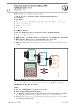
Страница 15: ...4 V 24 V 12 13 14 15 DI 2 16 17 18 DI 4 DI 5 DI 0 DI 1 DI 3 0 V 24 V 10 0 V DI1 DI2 DI3 DI4 DI5 230 V DO1 DO C 5 T1 T2 6 DO C DO 0 7 DO 2 9 DO 1 8 DO2 T1 T2 N max 200 mA 24 V K1 K1 external supply supply inputs 2CDC 342 009 F0207 free inputs signals directly to the fieldbus With parameter Check back 1 Auxiliary contacts the digital input DI0 is used to survey the contactor default 2 Motor current ...

Страница 16: ...e available with electronic interface only 5 Also available with electronic interface AF50 to AF185 Remark Spark suppression is necessary for all types except the AF types to keep resonable lifetime Interfacing larger contactors with electronic interface AF types Fig 3 2 Connection of contactors with electronic interface AF types to the UMC22 Remark Slide switch on the left side to position PLC up...

Страница 17: ...4 V 24 V 24 V 11 24 V 2CDC 342 010 F0207 Contactor type A45 and larger Spark supression Short circuit protection device e g BS6 30 10 28 For check back the auxiliary contact of the main contactor has to be used external supply supply inputs 3 2 2 Connection of contactors continued Interfacing contactors with peak current 0 5 A Types A50 and larger Fig 3 3 Connection of contactors with peak current...

Страница 18: ...3 2 3 1 U2 W2 V2 V1 W1 U1 UMC 22 U2 W2 V2 V1 W1 U1 400 V 690 V W2 U1 U2 V1 W1 V2 UMC 22 U2 W2 V2 V1 W1 U1 400 V 690 V V1 W1 U1 W2 U2 V2 UMC 22 U2 W2 V2 V1 W1 U1 400 V 690 V Star Power line 690 V Delta Power line 400 V 冑3 wiring Power line 400 V Example for motor Motor rating plate Example for motor Motor rating plate Example for motor Motor rating plate 4 9 A 2 8 A 4 9 A 2 8 A 4 9 A 2 8 A Paramete...

Страница 19: ...urrents up to 850 A space saving combinations are recommended Fig 3 5 UMC22 FBP with external current transformer for higher currents Type Korc type Recommended current range A Current factor Default 1 0 Secon dary current range A Hole area WxH mm2 Max wire size mm2 Link kit bar type for contactor Order code see chapter 6 Star Delta 冑3 wiring Star Delta 冑3 wiring UMC22 stand alone 0 24 63 0 42 109...

Страница 20: ...hall be increased to about 5 cm or the UMC shall be rotated by 90 degrees or the motor wires shall be loop through the UMC22 2 to 5 times When looping the motor wires multiple times the parameter Current Factor must be adjusted accord ing the number of loops I e the parameter must be set to two if the wires are looped through the UMC22 two times Two to five loops are supported The displayed curren...

Страница 21: ...ldbuses Normally the slave address is set by the Control Panel that means the slave address is directly adjusted and stored in the UMC22 Immediately when mounted or when the combination is switched on the address is monitored The address can be changed by menu point Change address 8 2 2 and 4 3 4 An other way to adjust the address in the FieldBusPlug is to use the Addressing Set CAS21 FBP 0 Interf...

Страница 22: ...tion starts Case 4 The UMC22 FBP and the FieldBusPlug contain the same address Operation and communication starts Case 5 The UMC22 FBP and the FieldBusPlug contain different addresses The behaviour of the UMC22 FBP depends on the setting of the parameter Address check Case 5a Address check Off 0 default The FieldBusPlug stores the address received from the UMC22 Operation and communication starts ...

Страница 23: ...e selected Other Programming Tools offer a menu point to read the GSD configuration file or may request separate configuration files for different devices With the definition of the Byte addresses the addresses of the bits and words are automatically defined Telegram data Word W Byte B Bits x Data bits 7 0 Input to PLC Monitor IW1 4 IB1 8 IB1 9 IX1 4 0 1 4 7 IX1 4 8 1 4 15 WARNING RUN REVERSE DI5 ...

Страница 24: ...UMC22 is switched off and on the start of the motor needs a new 0 to 1 transition of the Run signal Switching On Run and Off is possible when the UMC22 is parametrized with one of the motor controlling Control functions e g Direct starter Star Delta starter etc The exceptions are Transparent and Overload relay Switching On Run and Off can be done via control system via Control Panel via digital in...

Страница 25: ... panel control mode the control station sends the command bit AUTO MODE 0 in the command telegram Details see 4 3 4 and 8 2 3 Remark If the connection to the control system is interrupted control station problem or fieldbus interrupted the command AUTO MODE is regarded as 0 Stop the motor via Control system command OFF Under all circumstances dominating against RUN FORWARD or RUN REVERSE independe...

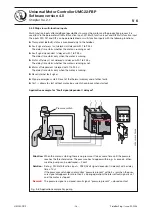
Страница 26: ...is running or not Motor off dependent delayed with 1 to 255 s The delay time starts only when the motor is running Reset internal fault signal Prepare emergency start Reset of the thermal memory and of other faults Test allows to start without motor no current check back when started Application example for Fault signal dependent delayed Chapter 3 4 2 1 Pressure switch 2CDC 342 039 F0206 Situation...

Страница 27: ...s fault inputs Switch on motor via digital input DI4 or DI3 if local control is parameterized or via Control Panel or with command RUN FORWARD or RUN REVERSE from control station via fieldbus Emergency start via control system fieldbus Set Parameter Emergency by PLC On default is Off 4 3 4 enables the UMC22 FBP to accept the command PREPARE EMERGENCY START Send command PREPARE EMERGENCY START 0 1 ...

Страница 28: ...ce is dominant and inhibits the start of the motor or stops an already running motor L006 and L008 The stop input must be connected to 24VDC if unused Fwd or Rev signal DI3 DI4 Relais Output UMC Stop signal by bus or panel Stop signal DI5 2CDC342034F0207 L007 and L009 The stop input must be connected to ground or left open if unused Fwd or Rev signal DI3 DI4 Relais Output UMC Stop signal by bus or...

Страница 29: ...ance personnel to perform timely maintenance The following figure shows how the earth fault sensor CEM11 can be connected to the UMC22 1 2 3 4 L1 L2 L3 through hole diameter 20 mm 35 mm 60 mm CEM11 Earth Leakage Monitor with current transformer DIN rail mounting unit also possible mounting with screws UMC22 24 V supply output digital input n c contact with selectable delay time DI2 CEM11 output is...

Страница 30: ...current high and low threshold are related to parameter 14 4 Configure the threshold when an earth fault should be signalled to the UMC The current must be directly configured at the earth fault monitor CEM11 itself See the technical manual for further details In the following figures the behaviour of UMC22 is shown in dependency to parameter 21 Example If the motor should trip if for at least 16 ...

Страница 31: ...r with intergated PTC sensors 2CDC 342 011 F0207 When the motor winding temperature reaches the PTC sensor s temperature rating the PTC sensor s resistance transitions from a low to high value UMC22 is able to perform PTC supervision with the option of enabling PTC fault trip or PTC fault war ning Beside that UMC22 detects the following erroneous conditions in relation to the PTC inputs Broken wir...

Страница 32: ...g no connection to the bus master or configuration error or parameters not valid 3 7 Signalling 3 7 1 Infos available on the LEDs Connection to the device Green on red off normal data exchange Green off red off check power supply Both LEDs flashing self test One of the LEDs flashing no connection to the UMC22 configuration data of UMC22 are missing green ready for operation yellow motor running ov...

Страница 33: ... Password panel control The access is arranged in three levels Monitoring Starts with menu point address offers only to check not to modify values and parameters Edit 1 Needs password and allows to change parameters during commissioning Password panel control to start and stop the motor via Control Panel Edit 2 Accessible via Edit 1 to change parameters that are used mainly associated with the ele...

Страница 34: ...l is activated it is still possible to enter other menu points of the Control Panel e g to change parameters etc Regarding the three level access only the Monitoring level has been changed LOC FWD REV LOC FAULT FWD LOC OUTPUT FWD LOC FWD FAULT C LOC A OUTPUT FWD current absolute start stop toggle stop reverse toggle fault flashing example of fault run cooling time running Supposed Parameter Local ...

Страница 35: ...check back fault 1 F006 2 Relay 1 check back fault 1 F007 2 Relay 0 check back fault 1 F008 2 Warning Byte 2 Motor current high threshold 1 Motor current low threshold 1 Cooling time running C 2 Self test running buSy 2 Emergency start prepared Warning Byte 3 If Parameter out of range Pamameter number leading two stages of the parameter e g 02 Current factor If Self test fauled Self test error num...

Страница 36: ...dress and informs the control system that the connected device is lost After mounting and connecting a new UMC22 the control system will be informed that the missing device is connected to the FieldBusPlug again supposed that the new UMC22 contains an invalid address A Attention If the exchanged UMC22 contains a valid address and the parameter Address check is not active the FieldBusPlug takes ove...

Страница 37: ...additional 2 bytes that concern the number of diagnosis bytes and status of the slave Configuration Modern fieldbuses such as PROFIBUS DP V0 V1 and DeviceNet fix the configuration data using the appropriate configuration files e g xxx GSD xxx EDS and write it automatically into the FieldBusPlug during power up Most of the FieldBusPlug types compare the configuration data sent by the UMC22 with the...

Страница 38: ...DI2 UMC input DI1 UMC input DI0 UMC input Monitoring telegram analog sent from the UMC22 to the control system Bit No 7 LSB 6 5 4 3 2 1 0 MSB Byte 0 Byte weight low Byte weight high MOTOR CURRENT of Set current Byte 1 Remark Some fieldbuses transfer digital input signals together with analog input signals in words Command telegram digital only sent from the control system to the UMC22 Bit No 7 6 5...

Страница 39: ...load trip fault trip 2 Motor blocked F002 2 Communi cation fault F003 2 Parameter out of range F004 2 Current check back fault 1 F005 2 Relay 2 check back fault 1 F006 2 Relay 1 check back fault 1 F007 2 Relay 0 check back fault 1 F008 2 2 OLS 0 1 without open command F006 2 CLS 0 1 without close command F006 2 CTS 1 0 but not CLS intermediate position F008 2 1 War ning Byte 2 Motor current high t...

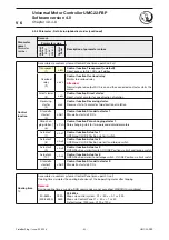
Страница 40: ...rection is accepted only when Reverse lock out time is over 5 LOCAL CONTROL 0 Local control is not active 1 Local control via Control Panel or digital inputs is activated RUN commands of the control system are ignored Details see chapter 4 3 4 6 FAULT 0 No fault exists 1 Any Fault condition exists Overload no check back when started etc Details see Diagnosis telegram Fault Bytes 0 and 1 Fault must...

Страница 41: ...nsition Internal test of the HW and SW starts memory mea suring channels etc The self test can only be started when the motor is Off Otherwise the signal Self test failed is set 4 PREPARE EMERGENCY START 0 1 transition Resets the UMC22 thermal memory to cold motor the cooling time and the blocking signal 1 Prepare emergency start of the motor Signal is only accepted by the UMC22 when the pa ramete...

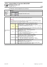
Страница 42: ...out a close command Reason e g faulty contact 5 F011 Fault signal on DI0 DI1 or DI2 Fault At least one multi function input has a fault signal 0 signal e g from a thermistor module Assumption At least one multi function input is parameterized as Multi function input 001 Fault signal always not delayed closed circuit principle 6 F010 Self test failed Fault Self test has failed or was started during...

Страница 43: ...ng on or motor current is already flowing 300 ms after swit ching off Assumption Parameter Check back Current 4 F004 Parameter out of range Fault Received parameter exeeds high or low limit The accompannying parameter number is shown in Diag nosis Byte 3 5 F003 Communication fault Fault UMC22 does not receive valid telegramms control system fieldbus or FieldBusPlug is out of order or interrupted o...

Страница 44: ...shold is activated 7 Motor current high threshold Warning Motor current is above the high threshold current Assumption Parameter High current threshold is activated 3 0 7 Parameter number Selft test fault number Neither Parameter numbers above 27 are not accepted para meter numbers are only possible for buses that allow access to single parameters Nor Self test fault number for service only Else 0...

Страница 45: ...l Panel allows to set most of the parameters 8 1 As a special feature the Control Panel can be used to read the complete parameter set of a paramete rized UMC22 and to transfer it to another UMC22 8 2 3 Remark Some parameters are taken over with power up others during motor off Provided that the internal fault bit is not set 4 3 1 Parameter groups Access via control system and or Control Panel The...

Страница 46: ...ssing Set CAS21 FBP 0 Password panel control 8 1 4 and 8 2 2 Switch on and off motor Dominating against control system but needs password Password Password needed for entering Menu level 2 and 3 of Control Panel Change password Change password for entering Menu level 2 and 3 of Control Panel Bus connection Can be set to Off when UMC22 is used stand alone without connection to a control system Para...

Страница 47: ...urrent threshold 100 800 Set current step 5 150 30 motor off 10 2 Cooling time 30 3600 s step 0 1 s 120 s 1200 motor off 11 1 Automatic fault reset Disabled 0 Autoreset 1 Disabled 0 motor off 12 1 Control function Transparent 1 Overload relay 2 Direct starter 3 Transparent 1 motoroff 3 13 1 Check back Auxiliary contontacts 1 Motor current 2 Simulation 3 Motor current 2 motor off 14 2 Start up time...

Страница 48: ...tion Range Default value text version Default digital take over after 1 22 1 Local control Off 0 On 1 002 2 003 3 004 4 005 5 006 6 007 7 008 8 009 9 Off 0 motor off 23 1 Blocking current threshold 0 800 Set current step 5 800 160 motor off 24 1 Fault output Off 0 On 1 blink 3 Off 0 motor off 25 1 Number of trips 0 255 step 1 0 0 read only 26 1 Address check Off 0 On 1 Off 0 power up 1 but only wh...

Страница 49: ... 0 24 3200 00 A step 0 01 A 0 5 A 50 motor off 7 4 8 low 9 5 10 Trip class Class 5 Class 10 Class 20 Class 30 Value 0 1 2 3 Class 10 1 motor off 11 DI0 Multi function input 000 to 048 Transparent 000 motor off 6 12 Phase loss protection Off 0 On 1 2 3 4 5 6 7 On 1 motor off Please read the safety remark in subsection 4 3 4 13 13 DI1 Multi function input 000 to 048 Transparent 000 motor off 7 14 Lo...

Страница 50: ... 27 low 14 28 reserved 29 reserved 15 30 reserved 31 Emergency by PLC Off 0 On 1 Off 0 motor off 16 32 reserved 33 reserved 17 34 reserved 35 reserved 18 36 Address check Off 0 On 1 Off 0 power up 37 Bus fault reaction Relays off 0 Outputs retain status 1 Relays off 0 motor off 19 38 DI2 Multi function input 000 to 089 Transparent 000 motor off 39 Local control Off 0 On 1 002 2 003 3 004 4 005 5 0...

Страница 51: ...ntrol Panel menu point A rES Only for control function Overload relay due to safety considerations Disabled 0 AroF Automatic fault reset off default Acknowledge via Control Panel or fieldbus necessary to reset fault To switch on again cooling time must be elapsed Autoreset 1 Aron Automatic fault reset activated Automatic reset of fault when fault condition is off and cooling time has elapsed Fault...

Страница 52: ... or interrupted Relays off 0 b oFF Relays off default Relay outputs of UMC22 will be switched off if a bus fault occurs Outputs retain status 1 b rEt Outputs retain status According to the control function the relay outputs of UMC22 which are used for motor control the retain their status if a bus fault occurs For Transparent mode this means that all 3 relays de energize Change password Only acces...

Страница 53: ... function Star delta starter 1 Star delta start via 2 DOs Pole chan ging starter 1 6 c Pch Control function Pole changing starter 1 Pole changing start for two pole and dahlander motors Actuator 1 7 c Ac1 Control function Actuator 1 OPEN and CLOSE Position via limit switch Actuator 2 8 c Ac2 Control function Actuator 2 OPEN and CLOSE Position via limit and torque switch Actuator 3 9 c Ac3 Control ...

Страница 54: ...1 Current range 0 24 63 A default Adjustment via control system 1 or 100 Both values are identified as current factor 1 100 If 1 or 100 has to be set depends on the version of the configuration file GSD EDS Adjustment via Control Panel 001 0 173 001 7 Current factor 1 73 Current range 0 4 109 A needed for 冑3 circuits Adjustment via control system 173 Value 173 corresponds with current factor 1 73 ...

Страница 55: ...ction input the inputs DI0 DI1 and DI2 can be parameterized as multi function inputs with the following functions Transparent default status is monitored only to the fieldbus Fault signal always not delayed or delayed with 1 to 255 s The delay time starts whether the motor is running or not Fault signal dependent delayed with 1 to 255 s The delay time starts only when the motor is running Motor of...

Страница 56: ...f 001 010 018 P 001 P 010 P 018 Fault signal always not delayed or delayed DIx 1 fault free status DIx 0 Starts the delay time whether the motor is running or not When delay time has elapsed the internal fault signal is set und the motor is stopped RUN commands will be only accepted when the fault has been reset Reset of fault is only possible if DIx 1 again Remark DI0 Due to compatibility reasons...

Страница 57: ... circuit Parameter value Delay time Parameter value Delay time 002 resp P 002 0 s 024 resp P 024 16 s 020 resp P 020 1 s 025 resp P 025 32 s 021 resp P 021 2 s 026 resp P 026 64 s 022 resp P 022 4 s 027 resp P 027 128 s 023 resp P 023 8 s 028 resp P 028 255 s 030 038 P 030 P 038 Fault signal dependent delayed DIx 1 fault free status DIx 0 Starts the delay time but only if the motor is running or i...

Страница 58: ...y accepted when DIx 1 again delay Command RUN FORWARD Motor running Signal on DI closed circuit delay Parameter value Delay time Parameter value Delay time 044 resp P 044 16 s 040 resp P 040 1 s 045 resp P 045 32 s 041 resp P 041 2 s 046 resp P 046 64 s 042 resp P 042 4 s 047 resp P 047 128 s 043 resp P 043 8 s 048 resp P 048 255 s 007 P 007 Reset of internal fault signal 1 signal at one of the in...

Страница 59: ...MC22 thermal memory cooling time and other faults DIx 1 continuously fault signals on DIs are ignored if parameterized Remark Not influenced still effective motor off signals on DIx if parametrized check back fault current or auxiliary contacts bus fault if Bus fault reaction Relays off limit and torque signals of the actuator The motor can be started with a 0 1 transition of the RUN command under...

Страница 60: ...1 or P 081 2 s 085 089 or P 085 P 089 25 s 082 or P 082 4 s 083 or P 083 8 s 060 069 P 060 P 069 Earth fault monitoring Trip Warning Parameter value Delay time Parameter value Delay time 060 or P 060 1 s 064 or P 064 16 s 061 or P 061 2 s 065 069 or P 065 P 069 25 s 062 or P 062 4 s 083 or P 063 8 s 070 079 P 070 P 079 Earth fault monitoring Warning Star up inhibit Parameter value Delay time Param...

Страница 61: ...ed default Output DO2 is free available On 1 Fo on Fault output activated light steady Output DO2 is used for fault indication blink 3 Fo bl Fault output activated flashing Output DO2 is used for fault indication High current threshold 09 Accessible via control system only 100 800 20 160 100 800 x Set current step 5 100 5 x 20 Warning when motor current is above threshold after start up time has e...

Страница 62: ...ct panel control Local operation via DIs DI3 DI4 and DI5 active signal pulse Direct panel control actived 005 5 L 005 005 Direct panel control only Local operation via DIs DI3 DI4 and DI5 not used free available Direct panel control actived DI3 is only used for the control functions Reversing starter Pole changing starter and Actuator 1 4 006 6 L 006 006 Local operation via DI3 und DI4 1 signal as...

Страница 63: ... supposed the fieldbus can transmit the value Change value is only possible via Control Panel menu point oPho 0 65 535 00 00 65 53 Remark All hours are counted but the last digit position is not displayed on the Control Panel The displayed range of 00 00 65 53 corresponds with 0 65 535 Parameter lock Accessible via Control Panel menu point PA Lo only Locks writing the parameters via control system...

Страница 64: ... resistance transitions from a low to high value The Warning dissapears automatically after temperature is low and PTC sensors s resistance transitions from a high to low value The fault trip disappear after fault reset 0000 0 x PTC protection x 0 not active x 1 active any 0000 0 x 000 0 x Phase loss protection x 0 not active x 1 active any Phase loss protection active Fault if the actual current ...

Страница 65: ...ional starters Time starts running with the OFF command An Off command is nessesary between run forward and reverse that means between RUN FORWARD and RUN REVERSE command A RUN command into the other direction will be acepted only when the reverse lock out time has elapsed 2 36000 0002 3600 0 2 3600 s Adjustment via control system step 0 1 s 0 2 s 0 1 s x 2 Adjustment via Control Panel step 1 s 2 ...

Страница 66: ...00 0 24 63 A step 0 01 A 0 24 A 0 01 A x 24 at current factor 1 default 42 109 00 42 109 0 0 42 109 A step 0 01 A 0 42 A 0 01 A x 42 at current factor 1 73 for 冑3 circuits 5000 32000 0050 3200 1 3200 A step 0 01 A 50 A 0 01 A x 500 at current factor 10 for circuits with external current transformers with secundary currents of approx 5 A Set current 2 03 Accessible via control system or Control Pan...

Страница 67: ...ting time is over For actuator 1 4 Start surveying time fixed 3 s Current 1 Sd cu Current default For star delta starter 1 Change from star to delta when motor current 울 0 9 x Set current 1 Remark Current check back fault is generated if the Star delta starting time has elapsed before switching to delta For actuator 1 4 Start surveying time adjustable 3 s 12 5 of the parameter Run time limit Star ...

Страница 68: ... 14 Accessible via control system only Suppresses Blocking High current threshold Low current threshold signals until motor is in nor mal running status 0 600 s 0 6000 0 600 s step 0 1 s 600 s 0 1 s x 6000 Default value 1200 120 s Trip class 04 Accessible via control system or Control Panel menu point triP Overload calculation thermal memory Class 5 tr05 Trip class 5 Class 10 tr10 Trip class 10 de...

Страница 69: ...max 25 mm max diameter incl insulation 11 mm Set current range for overload protection UMC22 alone 0 24 63 A UMC22 with provided current transformer see chapter 6 50 850 A Overload protection for three phase motors acc to EN IEC 60947 4 1 Trip classes selectable by parameter 5 10 20 30 acc to EN IEC 60947 4 1 Tripping time for cold motor for 3 phase symmetrical loads Tripping time for warm motor f...

Страница 70: ... if UMC22 is not longer supplied Calculation continues for some minutes typ 20 min Cooling time parameter An appropriate value need to be set default 120 s The cooling time that need to be set depends on Motor size of the motor larger size longer cooling time After trip motor still rotating driven or standstill without ventilation longer cooling time Environment temperature higher tem perature lon...

Страница 71: ...urrent refer ring EN IEC 60947 1 and for particular installation situation referring EN IEC 60204 or VDE 298 4 resp 5 2 Controller unit Supply voltage 24 V DC 30 20 19 2 31 2 V DC including ripple Supply current incl inputs relays activated max 160 mA at 19 2 31 2 V DC Total device dissipation max 3 7 W Reverse polarity protection yes Number of digital inputs 6 DI0 DI5 relay outputs 3 DO0 DO2 PTC ...

Страница 72: ...250 V AC DC Lowest switched power for correct signals 1 W or 1 VA Switching capacity per relay contact acc to EN 60947 5 1 AC 15 240 V AC max 1 5 A electromagnetic load AC 15 120 V AC max 3 A electromagnetic load DC 13 250 V DC max 0 11 A electromagnetic load DC 13 125 V DC max 0 22 A electromagnetic load DC 13 24 V DC max 1 A electromagnetic load Total current all contacts terminal 5 or 6 max 4 A...

Страница 73: ...sensor chain 1 5 k Line lenght 2 5 mm2 2 x 250 m 1 5 mm2 2 x 150 m 0 5 mm2 2 x 50 m Isolation no 5 6 FieldBusPlug connection Mounting Plug connection fastening with sup plied screw Tightening torque of the fixing screw 0 8 Nm rotation 90 degree Suitable ABB FieldBusPlug types for PROFIBUS DP PDP21 FBP PDP22 FBP PDQ22 FBP Devicenet DNP21 FBP MODBUS MRP21 FBP AS Interface ASP22 FBP 5 7 Environmental...

Страница 74: ...0 Out V V Power T1 8 DO 1 7 DO 0 6 DO C 5 DO C 9 DO 2 8 7 6 5 9 T2 3 4 UMC22 READY MOT ON FAULT INT EXT Power Relay 230VAC 1A Inputs 24VDC DC 2CDC 342 036 F0b07 UMC22 FBP Universal Motor Controller UMC22 FBP Software version 4 0 FieldBusPlug Issue 02 2008 V 6 Chapter 5 8 1 5 8 Dimensions Fig 5 1 Dimensions of UMC22 FBP ...

Страница 75: ...gth 0 50 m 1SAJ 240 100 R1005 Cable length 1 00 m 1SAJ 240 100 R1010 Cable length 2 00 m 1SAJ 240 100 R1020 Cable length 5 00 m 1SAJ 240 100 R1050 PDQ22 FBP PROFIBUS DP 4 x PROFIBUS DP FieldBusPlug 1SAJ 240 200 R0050 DNP21 FBP DeviceNet Cable length 0 25 m 1SAJ 230 000 R1003 Cable length 0 50 m 1SAJ 230 000 R1005 Cable length 1 00 m 1SAJ 230 000 R1010 Cable length 5 00 m 1SAJ 230 000 R1050 MRP21 F...

Страница 76: ... mA 120 1 1000 2000 2800 4000 4800 6000 6800 1SAJ 929 200 R0060 External current transformers Type recommended current range a KORC 4L185 R 4 63 185 A 1SCA 022 193 R7830 b KORC 4L310 R 4 185 310 A 1SCA 022 181 R0760 c KORC 5L500 R 4 310 500 A 1SCA 022 208 R1010 d KORC 5L850 R 4 500 850 A 1SCA 022 208 R1440 Link kit bar for current transformers Type for contactor type a DT450 A185 AF145 AF185 1SAZ ...

Страница 77: ... 400 V K1 K1 T1 T2 external supply supply inputs 2CDC 342 015 F0207 Control Panel 7 Control functions Circuit arrangement description data and parameters time diagrams Illustration 7 1 UMC22 FBP Control function Direct starter Example Chapter 7 1 Content 7 Control functions 77 7 1 Transparent 78 7 2 Overload relay 81 7 3 Direct starter 85 7 4 Reversing starter 92 7 5 Star delta starter 1 100 7 6 S...

Страница 78: ... 1 Transparent The UMC22 parametrized with the Control function Transparent default behaves like an I O module with an integrated overload check The outputs DO0 DO2 and the inputs DI0 DI5 are directly connected to the fieldbus and are independent of the overload status 7 1 1 Circuit diagrams 7 1 1 1 Basis circuit Parameters to be changed 4 3 4 based on default Address via Control Panel or via Addr...

Страница 79: ...ow signal on DI2 if the parameter Fault input On In this case the monitoring signal FAULT is sent to the fieldbus the red LED lights on the FAULT signal on the Control Panel flashes but the outputs DO0 DO1 and depending on the parametrization DO2 are controlled via fieldbus commands as before If a motor overload is the cause of the fault signal the Cooling time is started additionally The Cooling ...

Страница 80: ... 1 DO2 1 UMC output DO1 UMC output DO0 UMC output Diagnosis telegram Bit No 7 6 5 4 3 2 1 0 Fault Byte 0 Self test failed F010 2 Fault signal on DI0 DI1 or DI2 1 F011 2 Fault Byte 1 Overload trip fault trip 2 Communi cation fault F003 2 Parameter out of range F004 2 Warning Byte 2 Motor current high threshold 1 Motor current low threshold 1 Self test running buSy 2 Self test running buSy 2 Emergen...

Страница 81: ...ovides excellent protection of a motor Dedicated to replace a standard overload relay stand alone operation can be selected via Control Panel setting the parameter Bus connection Off 7 2 1 Circuit diagram 7 2 1 1 Basis circuit Main features Parameters to be changed 4 3 4 based on default Motor contactor at output DO0 Control function Overload relay Set current 1 Overload protection parameters Bus ...

Страница 82: ... up of the UMC22 7 2 2 2 Fault behaviour All kinds of detected external and internal faults set the internal fault bit Result contact DO0 opens contact DO1 and DO2 if parameterized closes the monitoring signal FAULT is send to the fieldbus the red LED lights on and the FAULT signal on the Control Panel flashes If a motor overload is the cause of the fault signal the cooling time is started additio...

Страница 83: ...T SELF TEST Byte 1 DO2 1 UMC output Diagnosis telegram Bit No 7 6 5 4 3 2 1 0 Fault Byte 0 Self test failed F010 2 Fault signal on DI0 DI1 or DI2 1 F011 2 Fault Byte 1 Overload trip fault trip 2 Communi cation fault F003 2 Parameter out of range F004 2 Current check back fault 1 F005 2 Warning Byte 2 Motor current high threshold 1 Motor current low threshold 1 Cooling time running C 2 Self test ru...

Страница 84: ...ustration7 4 UMC22 FBP Control function Overload relay time diagram Overload Chapter 7 2 4 1 Overload relay FAULT FAULT RESET DO1 trip DO0 trip FAULT WARNING 2CDC 342 269 F0103 Diagnosis Commands received telegr UMC22 outputs Monitorings telegram LEDs Fault red Fault reset end of cooling time Fault UMC22 internal Cooling time running Overload ...

Страница 85: ...the Control function Direct starter provides excellent protection and control of a motor for one direction of rotation The connection to a fieldbus is made via the appropria te type of the FieldBusPlug 7 3 1 Circuit diagrams 7 3 1 1 Basis circuit Main features Parameters to be changed 4 3 4 based on default Contactor K1 at DO0 Control function Direct starter Check back by current Set current 1 Inp...

Страница 86: ...002 003 004 008 or 009 Set current 1 Overload protection parameters Address via Control Panel or Addressing Set Illustration 7 6 UMC22 FBP Control function Direct starter extended circuit UMC22 0 V 10 24 V 11 24 V 12 DI 0 13 DI 1 14 DI 2 15 DI 3 16 DI 4 17 DI 5 18 5 DO C T1 T2 7 DO 0 6 DO C 8 DO 1 9 DO 2 0 V DI0 DI1 DI2 DI3 DI4 DI5 24 V 24 V N DO1 230 V 690 400 V K1 Fwd 2 Off 3 K1 K1 T1 T2 externa...

Страница 87: ... with 1 to 255 s The delay time starts whether the motor is running or not Motor off dependent delayed with 1 to 255 s The delay time starts only when the motor is running Reset internal fault signal Prepare emergency start Reset of the thermal memory and of other faults Test Start without motor no current check back when started Remark DI0 DI1 and DI2 can be parametrized via fieldbus Only DI2 can...

Страница 88: ...rt of the motor After activation of the selected Control function the motor can be started with the bus command RUN FORWARD or via local control Emergency start 3 4 3 Emergency start needs two operations 1 0 1 transition of the signal PREPARE EMERGENCY START Command telegram or digital input DI0 DI1 or DI2 if parameterized Reset of the thermal memory to cold motor Reset of the cooling time Repair ...

Страница 89: ... sent to the fieldbus the red LED lights on and the FAULT signal on the Control Panel display flashes If parameterized the output DO2 switches on If a motor overload is the cause of the fault signal the cooling time is started additionally The Cooling time is a parameter and can be adjusted The running cooling time is shown on the Control Panel with C All faults except communication fault must be ...

Страница 90: ...E PREPARE EMERGENCY START SELF TEST RUN FORWARD OFF Byte 1 DO2 1 UMC output DO1 UMC output Diagnosis telegram Bit No 7 6 5 4 3 2 1 0 Fault Byte 0 Self test failed F010 2 Fault signal on DI0 DI1 or DI2 1 F011 2 Fault Byte 1 Overload trip fault trip 2 Motor blocked F002 2 Communi cation fault F003 2 Parameter out of range F004 2 Current check back fault 1 F005 2 Relay 0 check back fault 1 F008 2 War...

Страница 91: ...agram overload Chapter 7 3 4 1 Direct starter RUN FORWARD OFF RUN FORWARD OFF FAULT RESET FAULT WARNING FAULT DO0 2CDC 342 055 F0203 Check back Commands received telegram UMC22 outputs Monitorings telegram LEDs DI1 aux contact Motor current aux contact Motor on yellow Run Run Diagnosis telegram UMC22 internal Cooling time running Overload Fault red Over load Fault reset Run end of cooling time Coo...

Страница 92: ...ion Reversing starter provides excellent protection and control of a motor for two directions of rotation The connection to a fieldbus is made via the appropriate type of the FieldBusPlug 7 4 1 Circuit diagram 7 4 1 1 Basis circuit Main features Parameters to be changed 4 3 4 based on default Contactor K1 forward at output DO0 Control function Reversing starter Check back by current Set current 1 ...

Страница 93: ...ch On 3 Off 0 dominating Off closed circuit signal Fault K1 forward K2 reverse 7 4 1 2 Extended circuit Main features Parameters to be changed 4 3 4 based on default Contactor K1 forward at output DO0 Control function Reversing starter Check back by auxiliary contact at DI0 Check back Auxiliary contact Contactor K2 reverse at output DO1 DI2 Multi function input 001 Fault input at DI2 0 V signal fa...

Страница 94: ...delayed with 1 to 255 s The delay time starts whether the motor is running or not Motor off dependent delayed with 1 to 255 s The delay time starts only when the motor is running Reset internal fault signal Prepare emergency start Reset of the thermal memory and of other faults Test Start without motor no current check back when started Remark DI0 DI1 and DI2 can be parametrized via fieldbus Only ...

Страница 95: ... via local control Emergency start 3 4 3 Emergency start needs two operations 1 0 1 transition of the signal PREPARE EMERGENCY START Command telegram or digital input DI0 DI1 or DI2 if parameterized Reset of the thermal memory to cold motor Reset of the cooling time Repair and reset of other faults after fault reset a continuous communication fault as the only exception does not block emergency st...

Страница 96: ...is sent to the fieldbus the red LED lights on and the FAULT signal on the Control Panel display flashes If parameterized the output DO2 switches on If a motor overload is the cause of the fault signal the cooling time is started additionally The Cooling time is a parameter and can be adjusted The running cooling time is shown on the Cont rol Panel with C All faults except communication fault must ...

Страница 97: ...FAULT RESET AUTO MODE PREPARE EMERGENCY START SELF TEST RUN FORWARD OFF RUN REVERSE Byte 1 DO2 1 UMC output Diagnosis telegram Bit No 7 6 5 4 3 2 1 0 Fault Byte 0 Self test failed F010 2 Fault signal on DI0 DI1 or DI2 1 F011 2 Fault Byte 1 Overload trip fault trip 2 Motor blocked F002 2 Communi cation fault F003 2 Parameter out of range F004 2 Current check back fault 1 F005 2 Relay 1 check back f...

Страница 98: ...possible after OFF and after the Reverse lock out time has elapsed Restart in the same direction without regard of the Reverse lock out time Chapter 7 4 4 1 Revesing starter RUN REVSERE RUN FORWARD OFF OFF RUN REVSERE RUN FORWARD Reversing lock out time 2CDC 342 056 F0203 Check back Commands received telegram UMC22 outputs Monitoring telegram LEDs DO1 reverse Motor current aux contact Motor on yel...

Страница 99: ...wledged Chapter 7 4 4 2 Revesing starter RUN REVERSE RUN FORWARD OFF FAULT RESET FAULT RUN REVERSE RUN FORWARD OFF WARNING FAULT 2CDC 342 057 F0203 Check back Commands received telegram UMC22 outputs Monitorings telegram LEDs DO0 forward DI0 aux contact Motor current aux contact Motor on yellow Run forward Run forward Diagnosis telegram UMC22 internal Cooling time running Overload Fault red Over l...

Страница 100: ...erized with the Control function Star delta starter 1 provides excellent protec tion and control of a motor for one direction of rotation including the time or current controlled star delta transition The connection to a fieldbus is made via the appropriate type of the FieldBusPlug 7 5 1 Circuit diagram 7 5 1 1 Basic circuit Main features Parameters to be changed 4 3 4 based on default Contactor K...

Страница 101: ...features Parameters to be changed 4 3 4 based on default Contactor K3 star at output DO0 Control function Star delta starter 1 Contactor K5 delta at output DO1 Fault output On Contactor K1 main via auxiliary contacts of K3 and K5 Check back Auxiliary contacts DI2 Multi function input 001 Fault lamp at output DO2 Local operation via DIs On 002 003 004 008 or 009 Check back by aux contacts DI0 DI1 S...

Страница 102: ...tion inputs DI0 DI1 and DI2 4 3 4 Depending of the parameterization of the parameters DI0 Multi function input DI1 Multi function input and DI2 Multi function input the following functions are possible Transparent default status is monitored only to the fieldbus Fault signal always not delayed or delayed with 1 to 255 s The delay time starts whether the motor is running or not Fault signal depende...

Страница 103: ...elected control function the motor can be started with the bus command RUN FORWARD or via local control Depending on the parameter Star delta changeover mode the mode changes from star to delta Star delta changeover mode Current Default Changeover within the Star delta changeover time is requested otherwise the Current check back fault is generated Star delta changeover mode Time Changeover after ...

Страница 104: ...ctor coil opens the monitoring signal FAULT is sent to the fieldbus the red LED lights on and the FAULT signal on the Control Panel display flashes If parameterized the output DO2 switches on If a motor overload is the cause of the fault signal the cooling time is started additionally The Cooling time is a parameter and can be adjusted The running cooling time is shown on the Control Panel with C ...

Страница 105: ... SELF TEST Selbsttest RUN FORWARD Start vorwärts OFF aus Byte 1 DO2 1 UMC Ausgang Diagnosis telegram Bit No 7 6 5 4 3 2 1 0 Fault Byte 0 Self test failed F010 2 Fault signal on DI0 DI1 or DI2 1 F011 2 Fault Byte 1 Overload trip fault trip 2 Motor blocked F002 2 Communi cation fault F003 2 Parameter out of range F004 2 Current check back fault 1 F005 2 Relay 1 check back fault 1 F007 2 Relay 0 chec...

Страница 106: ...trol function Star delta starter 1 Timing diagram star delta start RUN FORWARD OFF RUN FORWARD OFF 2CDC 342 025 F0206 Check back Commands received telegram UMC22 outputs Monitoring signals telegram LED DO0 star DO1 delta Motor current Aux contact DI0 aux contact DI1 aux contact Motor on yellow RUN OFF Star delta starting time Changeover time 50 ms Chapter 7 5 4 1 Star delta starter 1 ...

Страница 107: ...ed telegram UMC22 outputs UMC22 internal Monitoring signals telegram Diagnosis telegram LEDs Motor current Aux contact DI1 aux contact Overload trip Cooling time running Motor on yellow Fault red RUN DO0 than DO1 Over load Fault reset end of colling time RUN RUN 7 5 4 3 Overload Illustration 7 15 UMC22 FBP Control function Star delta starter 1 Timing diagram overload Chapter 7 5 4 2 Star delta sta...

Страница 108: ...trol of a motor for one direction of rotation including the time or current controlled star delta transition The connection to a fieldbus is made via the appropriate type of the FieldBusPlug Differences to control function Star delta starter 1 For Star delta starter 2 the number of switching cycles is the same for all 3 relais Control function Star delta starter 2 does not offern a fault output 7 ...

Страница 109: ... Extended circuit Main features Parameters to be changed 4 3 4 based on default Contactor K3 star at output DO0 Control function Star delta starter 2 Contactor K5 delta at output DO1 Fault output Off Contactor K1 main via DO2 Check back Auxiliary contacts Check back by aux contacts DI0 DI1 DI2 Multi function input 001 DI0 DI1 DI2 Multi function inputs e g fault or stop inputs when parameterized Lo...

Страница 110: ...ult status is monitored only to the fieldbus Fault signal always not delayed or delayed with 1 to 255 s The delay time starts whether the motor is running or not Fault signal dependent delayed with 1 to 255 s The delay time starts only when the motor is running Motor off always not delayed or delayed with 1 to 255 s The delay time starts whether the motor is running or not Motor off dependent dela...

Страница 111: ...epending on the parameter Star delta changeover mode the mode changes from star to delta Star delta changeover mode Current Default Changeover within the Star delta changeover time is requested otherwise the Current check back fault is generated Star delta changeover mode Time Changeover after the Star delta changeover time independent of the actual current Emergency start 3 4 3 Emergency start ne...

Страница 112: ...ontactor coil opens the monitoring signal FAULT is sent to the fieldbus the red LED lights on and the FAULT signal on the Control Panel display flashes If parameterized the output DO2 switches on If a motor overload is the cause of the fault signal the cooling time is started additionally The Cooling time is a parameter and can be adjusted The running cooling time is shown on the Control Panel wit...

Страница 113: ...CY START NOT Start vorbereiten SELF TEST Selbsttest RUN FORWARD Start vorwärts OFF aus Byte 1 Diagnosis telegram Bit No 7 6 5 4 3 2 1 0 Fault Byte 0 Self test failed F010 2 Fault signal on DI0 DI1 or DI2 1 F011 2 Fault Byte 1 Overload trip fault trip 2 Motor blocked F002 2 Communi cation fault F003 2 Parameter out of range F004 2 Current check back fault 1 F005 2 Relay 1 check back fault 1 F007 2 ...

Страница 114: ...function Star delta starter 1 Timing diagram star delta start RUN FORWARD OFF RUN FORWARD OFF 2CDC 342 023 F0206 Check back Commands received telegram UMC22 outputs Monitoring signals telegram LED DO0 star DO1 delta Motor current Aux contact DI0 aux contact DI1 aux contact Motor on yellow RUN OFF Star delta starting time Changeover time 50 ms DO2 main Chapter 7 6 4 1 Star delta starter 2 ...

Страница 115: ...elegram UMC22 outputs UMC22 internal Monitoring signals telegram Diagnosis telegram LEDs Motor current Aux contact DI1 aux contact Overload trip Cooling time running Motor on yellow Fault red RUN DO2 and DO1 than DO2 Over load Fault reset end of colling time RUN RUN 7 6 4 3 Overload Illustration 7 19 UMC22 FBP Control function Star delta starter 1 Timing diagram overload Chapter 7 6 4 2 Star delta...

Страница 116: ...r 1 provides excellent pro tection and control of a Two pole or Dahlander motor for one direction of rotation The change from one speed to the other is possible immediately The connection to a fieldbus is made via FieldBusPlug 7 7 1 Circuit diagrams 7 7 1 1 Basic circuit Two Pole Motor Main features Parameters to be changed 4 3 4 based on default Contactor K81 at output DO0 Control function Pole c...

Страница 117: ...tch On 3 Off 0 dominating Off closed circuit signal 7 7 1 2 Extended circuit Two Pole Motor Main features Parameters to be changed 4 3 4 based on default Contactor K81 at output DO0 Control function Pole changing starter 1 Contactor K91 at output DO1 Fault output On Fault lamp at output DO2 Check back Auxiliary contacts Check back by aux contacts on DI0 DI2 Multi function input 001 DI0 DI1 DI2 Mul...

Страница 118: ...l K81 speed 1 K91 spped 2 Remark Output DO1 controls contactor K2b Do not change Illustartion 7 22 UMC22 FBP Control function Pole changing starter 1 Dahlander Motor Basic circuit Chapter 7 7 1 3 Pole changing starter 1 7 7 1 3 Basis circuit Dahlander Motor Main features Parameters to be changed 4 3 4 based on default Contactor K81 at output DO0 Control function Pole changing starter 1 Contactor K...

Страница 119: ...witch On 3 Off 0 dominating Off closed circuit signal Chapter 7 7 1 4 Pole changing starter 1 Illustartion 7 23 UMC22 FBP Control function Pole changing starter 1 Dahlander Motor Extended circuit 7 7 1 4 Extended circuit Dahlander Motor Main features Parameters to be changed 4 3 4 based on default Contactor K81 at output DO0 Control function Pole changing starter 1 ContactorK91b at output DO1 Faul...

Страница 120: ...ayed with 1 to 255 s The delay time starts whether the motor is running or not Fault signal dependent delayed with 1 to 255 s The delay time starts only when the motor is running Motor off always not delayed or delayed with 1 to 255 s The delay time starts whether the motor is running or not Motor off dependent delayed with 1 to 255 s The delay time starts only when the motor is running Reset inte...

Страница 121: ...ted with the bus command RUN FORWARD speed 1 contactor K1 or RUN REVERSE speed 2 contactors K2a and K2b or via local control Change of the speed A B A is possible without restriction Between the two speeds a minimal change over time of about 50 ms is waited after current 0 or auxiliary contact off resp Emergency start 3 4 3 Emergency start needs two operations 1 0 1 transition of the signal PREPAR...

Страница 122: ...oil opens the monitoring signal FAULT is sent to the fieldbus the red LED lights on and the FAULT signal on the Control Panel display flashes If parameterized the output DO2 switches on If a motor overload is the cause of the fault signal the cooling time is started additionally The cooling time is a parameter and can be adjusted The running cooling time is shown on the Control Panel with C All fa...

Страница 123: ...AUTO MODE PREPARE EMERGENCY START SELF TEST RUN FORWARD OFF RUN REVERSE Byte 1 DO2 1 UMC output Diagnosis telegram Bit No 7 6 5 4 3 2 1 0 Fault Byte 0 Self test failed F010 2 Fault signal on DI0 DI1 or DI2 1 F011 2 Fault Byte 1 Overload trip fault trip 2 Motor blocked F002 2 Communi cation fault F003 2 Parameter out of range F004 2 Current check back fault 1 F005 2 Relay 0 1 check back fault 1 F00...

Страница 124: ...N FORWARD approx 50 ms 2CDC 342 279 F0203 Check back Command received telegram UMC22 outputs Monitoring telegram LEDs DO1 contactor K2a K2b Motor current aux contact Motor on yellow Run K1 UMC22 internal min changeover time Run K2 DO0 contactor K1 7 7 4 Timing diagrams 7 7 4 1 Change speed Illustration 7 24 UMC22 FBP Control function Pole changing starter 1 Timing diagram change speed ...

Страница 125: ...ULT 2CDC 342 280 F0203 Check back Commands received telegram UMC22 outputs Monitorings telegram LEDs DO0 than DO1 DI1 Aux contact Motor current Aux contact Motor on yellow Start Start Diagnosis telegram UMC22 internal Cooling time running Overload Fault red Over load Fault reset Start Cooling time elapsed Cooling time Illustration 7 25 UMC22 FBP Control function Pole changing starter 1 Timimg diag...

Страница 126: ...or 4 DI0 DI1 for Open Closed limit switches Reverse lock out time DI3 for Torque switches closed circuit DI2 Multi function input 001 DI2 Multi function input e g Fault inp for thermistor module if parametrized Run time limit Star delta starting time Local operation via Dis On 002 003 or 004 DI4 DI5 for Local Control if parametrized motor runs as long as signal 1 Fault output On Set current 1 and ...

Страница 127: ...3 24V 12 DI3 16 DI1 14 Open Torque Open Closed Closed 2CDC 342 020 F0205 Limit switches DI0 Motor off start only in Close direction DI1 Motor off start only in Open direction DI3 Fault motor stops Remark Torque signals are not necessary but can be used for surveillance After switching off the motor continu es to run for some milliseconds due to its rotating mass Adjustment of the Closed and Open l...

Страница 128: ... Torque happened du ring closing The start is possible only after fault acknowledge and only in the opposite direction Start is only possible in the opposite direction after resetting the fault The torque signal has to disappear within 0 5 s otherwise a fault is generated again 7 8 2 3 Actuator 3 Open position via limit switch only Closed position via torque and limit switches DI0 13 24V 12 DI3 16...

Страница 129: ...needed as Fault input it can be connected to the connection between the torque con tacts to find out which torque signal is active Run time Open Close The Run time limit Star delta starting time must be changed and should be set according to actuator datas Setting the Run time limit 1 s disables the supervision Starting from Open or Closed The limit switch has to open within the start surveying ti...

Страница 130: ...ning Motor off always not delayed or delayed with 1 to 255 s The delay time starts whether the motor is running or not Motor off dependent delayed with 1 to 255 s The delay time starts only when the motor is running Reset internal fault signal Prepare emergency start Reset of the thermal memory and of other faults Test Start without motor no current check back when started Remark DI2 can be parame...

Страница 131: ...speed 2 contactors K2a and K2b or via local control Emergency start 3 4 3 Emergency start needs two operations 1 0 1 transition of the signal PREPARE EMERGENCY START Command telegram or digital input DI0 DI1 or DI2 if parameterized Reset of the thermal memory to cold motor Reset of the cooling time Repair and reset of other faults after fault reset a continuous communication fault as the only exce...

Страница 132: ...nd the FAULT signal on the Control Panel display flashes If parameterized the output DO2 switches on If a motor overload is the cause of the fault signal the cooling time is started additionally The Cooling time is a parameter and can be adjusted The running cooling time is shown on the Control Panel with C All faults except communication fault must be acknowledged via fieldbus 4 2 1 via Control P...

Страница 133: ...T RUN FORWARD Open OFF RUN REVERSE Close Byte 1 DO2 1 UMC output Diagnosis telegram Bit No 7 6 5 4 3 2 1 0 Fault Byte 0 Sametime OLS and CLS F009 2 Self test failed F010 2 Fault signal on DI0 DI1 or DI2 1 F011 2 OLS 1 0 without close command F012 2 CLS 1 0 without open command F013 2 OLS 1 0 not within 3 s 3 after close command F014 2 CLS 1 0 not within 3 s 3 after open command F015 2 OTS 1 0 but ...

Страница 134: ...g 8 1 ACS100 PAN Control Panel for UMC22 FBP Chapter 8 Content 8 Control Panel Overview and menu 134 8 1 Overview Control Panel ACS100 PAN 135 8 1 1 Menu levels 135 8 1 2 Buttons on the Control Panel 136 8 1 3 Direct panel control 137 8 1 3 1 Current indication in or absolute 137 8 1 3 2 Menu levels for direct panel control 138 8 1 4 Comparison Password panel control and Direct panel control 139 8...

Страница 135: ...igital inputs digital outputs Show actual current Show set current 1 Number of starts Number of trips Star delta starting time Cooling time Operating hours Reversing lock out time Self test Address Set current 1 Set current 2 Trip class if password is 0000 default Local control Reset to default Star delta changeover mode Parameter transfer Bus connection Automatic fault reset Bus fault reaction Pa...

Страница 136: ...ut saving value Remark Returns to menu point Show address after 5 min if no button is pressed Exception Display Curr Go to next or previous menu point toggle round 2CDC 342 032 F0207 Procedure to adjust alphanumerical parameter values e g Parameter address Password Select the parameter you want to adjusted or changed with CURSOR Confirm selection with ENTER The actual adjusted value is shown The fir...

Страница 137: ...D LOC FWD FAULT C LOC A OUTPUT FWD current absolute start stop toggle stop reverse toggle fault flashing example of fault run cooling time running Supposed Parameter Local control 003 004 oder 005 AND Control station sends command AUTOMODE 0 OR Connection to control station interrupted Leave to other menu points e g to Set current Comes back to display current in after 5 min if no button is presse...

Страница 138: ...digital outputs Phase current in of set current Show set current 1 Number of starts Number of trips Star delta starting time Cooling time Operating hours Reversing lock out time Self test Address Set current 1 Set current 2 Trip class if password is 0000 default Local control Reset to default Star delta changeover mode Parameter transfer Bus connection Automatic fault reset Bus fault reaction Para...

Страница 139: ...command AUTO MODE 0 sent by the control system The Control Panel immediately changes to Direct panel control Similar when mounted or after power up Motor on Switching on and off of the motor is always possible under all circum stances independent of any parameter adjustment and command in the master telegram Switching on motor only when control station allows Switching off is always possible Safet...

Страница 140: ...ly 1 3 Fault messages 4 3 4 FAULT on the left side of the display is flashing Fault existing The menu goes directly to menu point Fault 1 3 x 1 3 1 1 1 3 y 1 3 1 1 first fault Acknowledge next fault Acknowledge The first of the existing faults is shown with ENTER Acnowledge of this fault with ENTER The next existing fault is shown imme diately Acknowledge this fault with ENTER No Fault existing 1 3 1...

Страница 141: ...ntrol resp even there is still a com munication fault Procedure Fault ENTER F00x ENTER Acno ENTER F MENU Fault MENU 1 3 4 Parameter out of range Received parameter exeeds high or low limit 1 3 5 Current check back fault No motor current within 300 ms after switching on or motor current is still flowing 300 ms after switching off Assumption Check back Motor current 1 3 6 OLS 0 1 without close comman...

Страница 142: ...ark This fault can not be achnowledged 1 3 11 Fault signal on DI0 DI1 or DI2 At least one Multi function input has a fault signal 0 signal e g from a thermistor module Assumption At least one multi function input is parametrized as Multi function input P 001 Fault signal always not delay ed closed circuit principle 1 3 12 OLS 1 0 without close command Actuator Actuator only Open limit signal disap...

Страница 143: ... via DI0 1 3 23 Fault on DI1 External fault signaled via DI1 1 3 24 Fault on DI2 External fault signaled via DI2 1 4 Digital input digital output 1 4 0 DI0 Example 0 signal at digital input 0 DI1 DI5 DO0 DO1 1 4 8 DO 2 Example 1 signal at digital output 2 1 4 9 Status DI DO Left place of the display d for digital I O Upper vertical lines of the 2 right places Signal status of the 3 digital outputs...

Страница 144: ...nge 1 5 1 show 0 24 63 00 A 0 42 109 0 A 50 3200 A Displayed range at Current factor 1 0 default Displayed range at Current factor 1 7 for 冑3 circuitry Displayed range at Current factor 10 for external current transformer secondary current 5 A 03 1 6 Show set current 2 4 3 4 Set current of winding 2 of 2 speed motors 1 6 1 show see show Set current 1 1 7 Version Firmware version of UMC22 18 1 8 Op...

Страница 145: ...r No Menu No Menu point name Display 7 segm Default Range Description remark take over 25 1 10 Number of trips 4 3 4 All trips are counted and displayed as 0000 0255 E 0xxx xxx 1 10 1 show 0 0 255 1 11 to 2 1 Edit 1 Go to Local control to parameters for motor protection and times with ENTER Chapter 8 2 1 6 ...

Страница 146: ...ent of the status of the command AUTO MODE If local control is activated RUN commands from the control system are ignored Entering and leaving local control does not influence the actual status of the outputs of the UMC22 Before removing the Control Panel this menu must be left otherwise the control system can not switch on the motor 2 2 1 switch motor on and off change direction Off is always poss...

Страница 147: ...ecimal point fits to the desired range More details see menu point Current factor and chapter 3 2 3 and 3 2 4 With Enter during motor off 2 4 1 show change 0 5 A 0 24 63 00 A 0 42 109 0 A 1 3200 A Displayed range at Current factor 1 00 default 2 stages before decimal point Displayed range at Current factor 1 7 internally corrected into 1 73 used for 冑3 circuitry up to 109 0 A with out external curr...

Страница 148: ...s 0 2 3600 s Show and change Reverse lock out time in steps of 1 s 16 2 9 Star delta starting time Only for Star delta starter Starts with the RUN command during motor off Run time limit 4 3 4 Only for Actuator 1 4 This time is used to survey the running time from Closed to Open position and vice versa see parameter Start surveying time Star delta changeover mode 2 9 1 show change 60 s 0 3600 s Sh...

Страница 149: ...r 19 2 12 Number of starts 4 3 4 All starts are counted but the three lower places are not displayed on the Control Panel The displayed range 0000 1000 corresponds with real 0 to 1 000 000 during motor off 2 12 1 show change 0 0 1 000 000 25 2 13 Number of trips 4 3 4 All trips are counted and displayed as 0000 0255 during motor off 2 13 1 show change 0 0 255 2 14 to 3 1 Edit 2 Go to operation lev...

Страница 150: ...ia fieldbus 3 2 2 Overload relay Similar to overload relay 3 2 3 Direct starter Direct start with check back 3 2 4 Reversing starter Reversing start with check back 3 2 5 Star delta starter 1 Star delta start via 2 DOs with check back 3 2 6 Pole changing starter 1 Pole changing start witch check back 3 2 7 Actuator 1 Actuator start type 1 witch check back 3 2 8 Actuator 2 Actuator start type 2 witc...

Страница 151: ... changed before or together with the Set current Depending on the Current factor the number of stages before the decimal point fits to the desired range More details see menu point Current factor and chapter 3 2 3 and 3 2 4 With Enter during motor off 3 3 1 show change 1 0 1 0 1 7 10 640 Current range 0 24 63 00 A de fault 2 stages before decimal point Current range 0 42 109 0 A 1 7 is internally c...

Страница 152: ... Off Phase loss protection not active PTC protection not active 3 4 2 On On Phase loss protection active PTC protection not active default 3 4 3 Off PTC Warn Phase loss protection not active PTC protection active with PTC warning 3 4 4 On PTC Warn Phase loss protection active PTC protection active with PTC warning 3 4 5 004 Phase loss protection not active PTC protection not active 3 4 6 005 Phase...

Страница 153: ... No local control No loc control No local control of any kind 3 5 2 Local operation only via DI3 DI4 DI5 1 DI3 Reverse true pulse DI4 Forward true pulse DI5 Off closed circuit pulse No Direct panel control via Control Panel 3 5 3 Local operation only via DI3 DI4 DI5 2 DI3 Reverse true pulse DI4 Forward true pulse DI5 Off true pulse No Direct panel control via Control Panel 3 5 4 Local operation vi...

Страница 154: ...d DI4 motor on as long as button pressed DI5 true pulse Direct control via Control Panel 3 5 9 Local operation via DI3 DI4 DI5 only Local operation via DI3 und DI4 motor on as long as button pressed DI5 closed circuit pulse 3 5 10 Local operation via DI3 DI4 DI5 only Local operation via DI3 und DI4 motor on as long as button pressed DI5 true pulse 13 3 6 Check back 4 3 4 during motor off 3 6 0 Aux...

Страница 155: ... via bus master fieldbus during motor off 3 7 00 Transparent P 000 Input status is monitored only to the fieldbus correspondes to former parameter Fault input DI2 Off 3 7 01 Fault signal always undelayed If the input DI2 0 the internal fault signal is set immmediately In the following Relays outputs open motor is stop ped fault is monitored to the fieldbus If parameter Fault output On out put DO2 is ...

Страница 156: ...esponds to parameter Check back Simulation For safety reasons it should be set via Control Panel only 3 7 09 Prepare emergency start Needed when the UMC22 has tripped and the cooling time is still running DIx 0 1 transition resets UMC22 thermal memory coo ling time and other faults DIx 1 continuously fault signals on DIs are ignored if parameterized Remarks Not influenced still effective motor Off ...

Страница 157: ...r fault acknowledge Remark The signals are monitored to the field bus without delay during motor off Menü No Display Delay time Menü No Display Delay time 3 7 10 1 s 3 7 15 32 s 3 7 11 2 s 3 7 16 64 s 3 7 12 4 s 3 7 17 128 s 3 7 13 8 s 3 7 18 255 s 3 7 14 16 s 3 7 19 reserved reserved 3 7 20 3 7 28 Motor off always delayed DI2 1 motor start is released is not stopped DI2 0 time starts indepen dend ...

Страница 158: ...No Display Delay time Menü No Display Delay time 3 7 30 1 s 3 7 35 32 s 3 7 31 2 s 3 7 36 64 s 3 7 32 4 s 3 7 37 128 s 3 7 33 8 s 3 7 38 255 s 3 7 34 16 s 3 7 39 reserved reserved 3 7 40 3 7 48 Motor off dependent delayed DI2 1 motor is not stopped DI2 0 motor start is not blocked de lay time starts earliest with motor start after delay time motor is stopped Menü No Display Delay time Menü No Disp...

Страница 159: ...th start up inhibit Menü No Display Delay time Menü No Display Delay time 3 7 70 1 s 3 7 74 16 s 3 7 71 2 s 3 7 75 3 7 79 25 s 3 7 72 4 s 3 7 73 8 s 3 7 80 3 7 89 Earth fault monitoring trip and warning with start up inhibit Menü No Display Delay time Menü No Display Delay time 3 7 80 1 s 3 7 84 16 s 3 7 81 2 s 3 7 85 3 7 89 25 s 3 7 82 4 s 3 7 83 8 s 24 3 8 Fault output 4 3 4 UMC22 output D02 can...

Страница 160: ...ange from star to delta when motor current 울 0 9 x Set current Remark Current check back fault is genera ted if the star delta starting time has elapsed before switching to delta For actuator 1 4 Start surveying time adjustable 3 s 12 5 of parameter Run time limit Star delta starting time 11 3 10 Automatic fault reset 4 3 4 Only for control function Overload relay due to safety considerations duri...

Страница 161: ...ower up transition 3 11 1 Connected to the fieldbus On Operation with fieldbus 3 12 Bus fault reaction 4 3 4 All cases when UMC22 does not receive valid telegrams either when the control system or the fieldbus or the FieldBusPlug is out of order or interrupted during motor off 3 12 1 Relays off Relays off Relay outputs of UMC22 will be swit ched off if a bus fault occurs 3 12 2 Relays retain status R...

Страница 162: ...eration hours Number of starts and Number of trips can be read out from or write into the UMC22 power up transition 3 14 1 Read parameters Control Panel reads out all parameter information from an UMC22 3 14 2 Set parameters Control Panel overwrites all parameter information in the UMC22 3 15 Reset to Default 4 3 4 power up transition 3 15 1 execute Sets all parameter values to default values exep...

Страница 163: ...elay 7 2 Pole changing starter 7 7 Dahlander starter 7 7 1 3 Two pole motor starter 7 7 1 1 Reversing starter 7 4 Star delta starter 1 7 5 Star delta starter 2 7 6 Transparent mode 7 1 Earth fault protection 3 5 External current transformer use of 3 2 4 Fault indication 3 7 4 Faults displayed on the Control Panel 8 2 1 3 7 4 Getting started 7 3 1 7 4 1 Higher currents above 63 A 3 2 4 Local contro...

Страница 164: ... 3 4 10 Multi function inputs DI0 DI1 and DI2 4 3 4 4 8 2 3 4 Fault signal delayed 4 3 4 5 8 2 3 6 Operation hours 4 3 4 12 8 2 2 4 Parameter transfer 4 3 4 12 8 2 3 10 Phase loss protection 4 3 4 13 8 2 3 2 PTC protection 4 3 4 13 8 2 3 2 3 6 Starts number of 4 3 4 11 8 2 2 4 Trips number of 4 3 4 12 8 2 2 4 PTC Thermistor protection 3 6 Supply 3 2 1 Switch on and off motor 3 4 Trip diagrams 5 1 ...

Страница 165: ... 165 UMC22 FBP FieldBusPlug Issue 02 2008 V 6 Universal Motor Controller UMC22 FBP Software version 4 0 ...

Страница 166: ... 166 UMC22 FBP Universal Motor Controller UMC22 FBP Software version 4 0 FieldBusPlug Issue 02 2008 V 6 Notes ...

Страница 167: ......

Страница 168: ...elheimer Straße 82 Postfach 101680 69123 Heidelberg 69006 Heidelberg Germany Germany Telephone 49 0 6221 701 0 Telefax 49 0 6221 701 240 E mail automation helpline desto de abb com Internet http www abb de stotz kontakt 2CDC 135 001 D0210 ...

Отзывы: