- 39 -
UMC22-FBP
Universal Motor Controller UMC22-FBP
Software version 4.0
FieldBusPlug / Issue: 02.2008
V 6
Chapter 4.2.1~2
4.2.1 Monitoring, command and diagnosis data - Overview (continued)
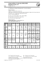
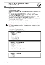
Diagnosis telegram
Telegram sent from UMC22 to control system.
Depending on the fi eldbus type the bus master requests the diagnosis telegram from the concerned slave
automatically or not, see appropriate FieldBusPlug description.
All faults can be acknowledged via:
control system: Command Byte 0, Bit 6 =1 (FAULT RESET)
Control Panel: menu point fault messages (FAuL)
multi-function input (if parameterized)
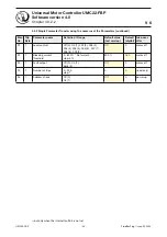
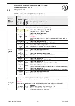
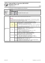
Diagnosis telegram
1) for all control functions except Actuator 1 to 4
2) for control function Actuator 1 to 4
for Bit No.
7
6
5
4
3
2
1
0
1)
Fault
Byte 0
-
Self test failed
F010
2)
Fault signal on
DI0, DI1
or DI2
1)
F011
2)
-
-
-
-
-
2)
Sametime
OLS and CLS
F009
2)
OLS 1
0
without
close
command
F012
2)
CLS 1
0
without
open
command
F013
2)
OLS 1
0
not within
3 s
4)
after
close
command
F014
2)
CLS 1
0
not within
3 s
4)
after
open
command
F015
2)
OTS 1
0
but not OLS
(intermediate
position)
F016
2)
1)
Fault
Byte 1
Overload (trip)
fault
trip
2)
Motor blocked
F002
2)
Communi-
cation fault
F003
2)
Parameter out
of range
F004
2)
Current
check-back
fault
1)
F005
2)
Relay 2
check-back
fault
1)
F006
2)
Relay 1
check-back
fault
1)
F007
2)
Relay 0
check-back
fault
1)
F008
2)
2)
OLS 0
1
without
open
command
F006
2)
CLS 0
1
without
close
command
F006
2)
CTS 1
0
but not CLS
(intermediate
position)
F008
2)
1)
War-
ning
Byte 2
Motor current
high threshold
1)
Motor current
low threshold
1)
-
Cooling time
running
°C
2)
-
Self test
running
buSy
2)
Emergency
start
prepared
-
2)
Run-time
exeeded
3)
1)
+
2)
War-
ning
Byte 3
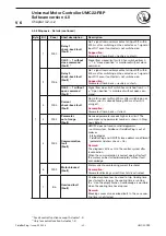
If Parameter out of range: Pamameter number (leading two stages of the parameter, e.g. "02" Current factor)
If Self test fauled: Self test error number (only for service)
In all other cases:
Phase loss
trip
2
Fault on DI2
F024
2)
Faut on DI1
F023
2)
Fault on DI0
F022
2)
Earth fault
F020
2)
PTC
short-circuit
F019
2)
PTC
wire break
F018
2)
PTC
temperature
F017
2)
OLS = "Open limit switch" (active signal)
CLS = "Closed limit switch" (active signal)
OTS = "Open torque switch" (closed circuit signal)
CTS = "Closed torque switch" (closed circuit signal)
1)
depending on the parameterization
2)
displayed on the Control Panel
3)
Run-time limit: max. running time open
close. Use Parameter
Star-delta starting time
.
4)
Start surveying time can be elongated (4.3.4)


