


Electrical
connection
CI/TTH200-EN
TTH200
EN - 17
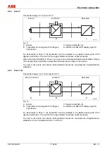
4.6.2 Zone
0
Transmitter design: II 1 G Ex ia IIC T6
Zone 0
Ex Zone 0
Safe area
A00146
B
C
ia
ia
J
A
D
i
a
Fig. 11
A Sensor
B Transmitter in housing with IP 20 degree
of protection
C Supply isolator [Ex ia]
D Interface for HMI LCD Display type AS
For instruments in Zone 0, the transmitter must be installed in a suitable housing with IP 20
degree of protection. The input for the supply isolator must have an [Ex ia] design.
When using the transmitter in Zone 0, you must ensure that impermissible electrostatic charging
of the temperature transmitter is prevented (observe the warnings on the device).
The user must ensure that sensor instrumentation meets the requirements of applicable Ex
standards.
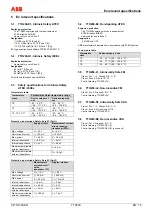
4.6.3 Zone 1 (0)
Transmitter design: II 2 (1) G Ex [ia] ib IIC T6
Zone 0 or Zone 1
Ex Zone 1
Safe area
A00146
B
C
ib
ia
J
A
D
i
a
Fig. 12
A Sensor
B Transmitter in housing with IP 20 degree
of protection
C Supply isolator [Ex ib]
D Interface for HMI LCD Display type AS
For instruments in Zone 1, the transmitter must be installed in a suitable housing with IP 20
degree of protection. The input for the supply isolator must have an [Ex ib] design.
The user must ensure that sensor instrumentation meets the requirements of applicable Ex
standards. It can be installed in Zone 1 or Zone 0.


