64/72
TLE Series 625 to 1000 PurePulse™ UL S2
UPS Installation Guide / REV-B
4.12
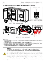
TLE Series 1000 - Wiring of “IP Ring Bus” (option)
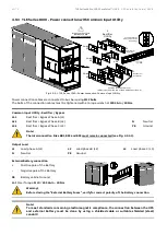
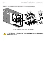
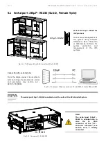
Fig. 4.3.7-1 TLE Series 1000 - Electronic bracket
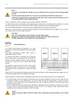
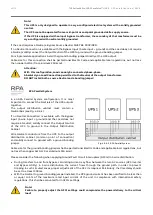
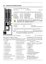
Fig. 4.3.7-2 TLE Series 1000 - IP Ring Bus fuses
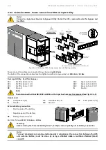
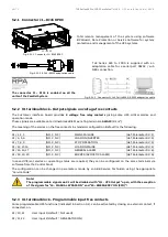
Fig. 4.3.7-3 TLE Series 1000 - Electronic bracket
Wiring rules:
-
To connect to XRB1 use 4-conductors, double insulated, 18AWG power cord, 300V rated, prepared with lugs 6-
32 in, tinned copper.
-
To connect to XRB2 use single AWG 18 conductors or power cord, tinned copper.
-
Cables must run into the pass-through conduit and leave the cabinet from the cut “B” on the bottom (Fig. 4.3.7-1).
-
After leaving the cabinet, cables must be run into conduits, per local wiring rules.
They shall not be accessible to end user and not likely to be stress by pulling.
Warning!
All maintenance and service works must be performed by an ABB Service Technician only!
The cover “A” must be always be mounted. If not serious injury or electrical shock could occur!
TLE Series 1000 with “IP Ring Bus” option:
In case of “IP Ring Bus” option be aware that external hazardous voltage can be supplied from the
IP cabinet (FU1, FU2, FU3 / Fig. 4.3.7-2) to the IM0278 (J19.10, J19.7, J19.4 / Fig. 4.3.7-3) and to the
connector XRB1 (Fig. 4.3.7-3) even after UPS shut down.
To remove the hazardous voltages it is necessary to manually open the IP cabinet fuses (FU1, FU2,
FU3 / Fig. 4.3.7-2), checking the presence of any voltage before working on the UPS.
Read carefully the documentation provided together with the external “IP Ring Bus” cabinet to
prevent electric shock.
Electronic bracket
E
P
O
E
P
O
- +
1
2
Q1
0 OFF
I ON
IP_Ring B
us_TLES_U
L_1000_S
2_UPS ele
ctronic br
acket_ABB
_01
A
B
IP Ring Bus cabinet
FIELD WIRES
FU3
1
2
BC
1
(I
PBU
SL
IMI
T:
C1
) %
FU2
1
2
BB1
(IP
BU
SL
IMI
T:
B1
) %
FU1
1
2
BA
1
(I
PBU
SL
IMI
T:
A1
) %
1-10-7-4
3-8-1-6
1-6-2-7-4-9
U
PS
O
ff
(N
O)
M
ai
nt
en
an
ce
(N
O
)
R
in
g
In
hib
it
ed
(NO
)
R
in
g
- L1
R
in
g
- L2
R
in
g
- L3
R
in
g
- N
1
2 3 4
1
2 3 4 5 6 7 8 9
TLE Series 1000 UL S2
P2
P2
P3 + P18
J_SSM2
J9
J6 J7
J18
Option in added into Electronic Bracket
J23
J24
J7 J8
J18
IM279
IM278
J21
J20
J19
10 11 12
XRB2
XRB1
B
ypa
ss
C
lo
se
d
(G
N
D
)
B
ypa
ss
C
lo
se
d (
+2
4V
)
R
in
gb
us
c
on
ne
ct
ed
(GN
D
)
R
in
g
b
us
c
o
nn
ec
te
d
(+
24
V
)
IM279
IM278
P2
P3
P1
XRB2
XRB1
IP-Ring-Bus_TLES_UL
_1000_S1_Electro
nic bracket_ABB_0
1
A
E
PO
E
PO
-
+
1
2
TLE Series 1000 UL - Electronic Bracket

