manualshive.com logo in svg
background image

INSTRUCTION HANDBOOK

1SDH002304A1001 - ECN000285442

EMAX 2 E2.2

Disassembly instructions

Содержание SACE Emax 2 E2.2

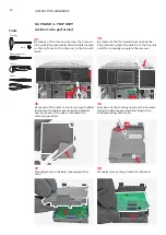
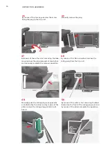
Страница 1: ... INSTRUCTION HANDBOOK 1SDH002304A1001 ECN000285442 EMAX 2 E2 2 Disassembly instructions ...

Страница 2: ......

Страница 3: ...er to section Unpacking and handling of Emax 2 Installa tion operation and maintenance instructions for the installer and the user document Improper lifting can result in death serious injury to persons and damage to the equipment never lift a circuit breaker above other people The trained personnel in charge of handling and lifting must use appropriate safe ty equipment Disassembly operations of ...

Страница 4: ...t 1 Trip unit back cover Mounted on the trip unit 1 Trip unit printed circuit board Mounted in the trip unit 1 4 micro I O assembly base Mounted on the terminal box 1 4 auxiliary contacts Mounted in the terminal box 1 Connectors Mounted on the terminal box 2 Connector with 2 microswitches Mounted on the terminal box 1 I O shaft Mounted on the terminal box 1 Terminal box case Mounted on the termina...

Страница 5: ... on the MID 1 RTC micro lever Mounted in the MID 1 MID main structure Mounted in the MID 1 Springs charging lever Mounted on the operating mechanism 1 Operating mechanism Mounted on the center of the circuit breaker 1 Auxiliary contacts cam Mounted on operating shaft assembly 1 Cam Mounted on operating shaft assembly 1 Lever Mounted on operating shaft assembly 1 Measuring module connector Mounted ...

Страница 6: ...it breaker 4 By means of the cross screwdriver unscrew the 4 screws fixing the front cover to the circuit breaker main structure 6 By means of the torx key unscrew the 2 screws fixing the 2 plugs to the front cover 3 Manually remove the racking in and out lever located in the bottom part of the circuit breaker 5 Manually remove the front cover 2 Manually remove the trip unit transparent cover Acti...

Страница 7: ...alling plug automatically separate from the T U Reset metal support 9 Manually remove the T U Reset assembly 8 By means of thr torx key unscrew the 2 screws fixing the T U Reset assembly to the front cover 12 By means of the torx key remove the 2 screws fixing the plug to the circuit breaker front cover 10 By means of the flat screwdriver remove the 2 benzings mounted on the T U Reset assembly ...

Страница 8: ... means of the cross screwdriver unscrew the 2 screws located behind the springs charging lever fixing the operating mechanism cover to the circuit breaker main structure and always by means of the cross screwdriver unscrew the screw located in the bottom right part of the operating mechanism cover fixing it to the circuit breaker main structure 16 Manually complete the removal of the operating mec...

Страница 9: ...tion Plastic and Metal 1 racking in and out lever Plastic and Metal 4 2 2 2 3 1 screws Metal 3 plugs Plastic 2 benzings Metal 1 pin Metal 1 spring Metal 1 T U Reset signalling plug Plastic 1 T U Reset support Metal 1 circuit breaker front cover Plastic 1 operating mechanism cover Plastic ...

Страница 10: ... screws fixing the 2 side walls located at both sides of the sliding contacts block to the circuit breaker main structure 20 Manually remove the base and the cover 19 Move the sliding contacts block as shown in the picture and by means of the torx key size 8 unscrew the 6 screws fixing the base and the cover 18 Manually remove the 2 side walls located on the sides of the sliding contact block ...

Страница 11: ...bly as indicated in the picture 24 Manually remove the auxiliary position contacts cap located on the left side of the sliding contacts block 26 By means of the flat screwdriver unhook the right side wall from the sliding contacts main assembly as indicated in the picture 22 Manually remove the sliding contacts block 21 By means of the flat screwdriver push up the 3 flat cables assemblies and the ...

Страница 12: ...e sides of each block slightly push them as indicated by the arrows and complete the removal of the 3 flat cables assemblies and of the connector cables assembly manually pulling them 32 By means of the pliers remove the 4 pins and the related nuts mounted at both sides of the sliding contacts base 27 By means of the flat screwdriver unhook the right side wall from the sliding contacts main assemb...

Страница 13: ...cs containing brominated flame retardants 1 right side wall Plastic SEPARATE TREATMENT Thermoplastics containing brominated flame retardants 1 sliding contacts label Adhesive paper 3 flat cables assemblies Plastic and Metal SEPARATE TREATMENT Thermoplastics containing brominated flame retardants 1 connector cables assembly Plastic and Metal SEPARATE TREATMENT Thermoplastics containing brominated f...

Страница 14: ...s of the torx key unscrew the 2 screws fixing the Ekip measuring blind plug to the Ekip measuring blind case 38 Manually remove the printed circuit board 35 By means of the cutter start removing the label located on the Ekip measuring blind module and by means of the pliers complete the removal operation 37 Manually remove the Ekip measuring blind case 34 By means of the flat screwdriver unhook th...

Страница 15: ...ip unit 44 By means of the flat screwdriver push the black connector as indicated by the arrow until it s totally unhooked and after manually complete the removal of the trip unit from the circuit breaker main structure 40 By means of the cross screwdriver unscrew the 4 screws fixing the trip unit to the circuit breaker main structure 39 By means of the flat screwdriver unhook the white connector ...

Страница 16: ...ated by the arrow and by means of the pliers remove the rating plug printed circuit board 48 By means of the flat screwdriver remove the rating plug from the trip unit 50 By means of the cutter start removing the label located on the front of the rating plug case and by means of the pliers complete the operation 46 Manually remove the plug 45 By means of the torx key unscrew the screw fixing the p...

Страница 17: ...driver unhook the display from the trip unit main structure 54 By means of the torx key unscrew the screw fixing the display to the trip unit main structure 56 Manually remove the display from the trip unit main structure 52 Manually remove the Ekip signaling 4K plug from the trip unit main structure 51 By means of the torx key unscrew the 2 screws fixing the Ekip signalling 4K plug to the trip un...

Страница 18: ...he flat screwdriver unhook the HMI box from the display 62 Manually separate the display and the HMI LCD cover 58 By means of the flat screwdriver remove the battery cover on the left side of the display 57 By means of the cutter start removing the trip unit front label and by means of the pliers complete the operation ...

Страница 19: ...t board from the display support 67 Manually separate the display from its printed circuit board 66 Manually remove the display support 68 Manually separate the gasket from the display 64 Manually remove the battery gasket 63 By means of the flat screwdriver remove the i TEST pushbutton from the HMI LCD cover ...

Страница 20: ...the trip unit back cover 72 By means of the cutter start removing the blind label located on the side of the trip unit main structure and by means of the pliers complete the operation 74 Manually remove the release case from the cover 70 Manually complete the removal operation of the backplane 69 By means of the torx key unscrew the 4 screws fixing the backplane to the trip unit main structure ...

Страница 21: ...label Adhesive paper 1 Ekip signalling 4K plug Plastic SEPARATE TREATMENT Thermoplastics containing brominated flame retardants 1 trip unit front label Adhesive paper 1 battery cover Plastic SEPARATE TREATMENT Thermoplastics containing brominated flame retardants 1 battery Battery SEPARATE TREATMENT Battery 1 HMI box Plastic 1 HMI LCD cover Plastic 1 i Test pushbutton Rubber 1 battery gasket Rubbe...

Страница 22: ...ure 82 By means of the torx key unscrew the 2 screws fixing the 4 micro I O assembly to the circuit breaker main structure 79 Manually unhook the connector indicated by the arrow fixing the terminal box case to the circuit breaker main structure 81 Insert the flat screwdriver as indicated in the picture slightly push it in the direction indicated by the arrow and after complete the removal of the ...

Страница 23: ...e 3 screws fixing the terminal box case to the circuit breaker main structure 88 Manually pull and remove the connector located in the right part of the terminal box case 84 By means of the flat screwdriver separate the 4 micro I O assembly cover from the 4 micro I O assembly base 83 Push the flat screwdriver in the direction indicated by the arrow and after manually remove the microswitch assembl...

Страница 24: ...p 92 Manually remove the I O shaft group 94 By means of the flat screwdriver remove the benzing mounted on the I O shaft group 90 By means of the flat screwdriver push the 2 connectors as indicated by the arrow and after manually complete the removal 89 By means of the flat screwdriver unhook the 2 microswitches from their support and after separate the microswitches support from the rest of the c...

Страница 25: ...contacts Plastic and Metal SEPARATE TREATMENT Thermoplastics containing brominated flame retardants 2 connectors Plastic SEPARATE TREATMENT Thermoplastics containing brominated flame retardants 1 connector with 2 microswitches Plastic SEPARATE TREATMENT Thermoplastics containing brominated flame retardants 1 microswtiches support Plastic 1 spring Metal 1 benzing Metal 1 pin Metal 1 I O shaft Plast...

Страница 26: ... fixing the cable guide to the circuit breaker main structure 101 By means of the flat screwdriver unhook the flap from the cable guide and complete the removal of the cable guide 98 By means of the torx key unscrew the 2 screws fixing the cable guide to the circuit breaker main structure 100 Manually unhook the connector fixing the cable guide to the circuit breaker main structure 97 Manually rem...

Страница 27: ...f the flat screwdriver remove the clip and after manually complete the removal Disassembled parts 1 2 1 screws Metal 1 left MID Plastic and Metal SEPARATE TREATMENT Thermoplastics containing brominated flame retardants 1 cable guide Plastic 1 clip Plastic ...

Страница 28: ...oss screwdriver unscrew the 2 screws fixing the cover to the CD 108 By means of flat screwdriver remove the benzing 105 Lift the circuit breaker using the lifting plates and let the CD disconnect by gravity 107 Manually remove the cover 104 By means the Allen key unscrew the screw located in the front part of the circuit breaker that fixes the CD to the main structure of the circuit breaker Cross ...

Страница 29: ...icator 114 By means of the flat screwdriver remove the benzing and after manually remove the feeler 110 By means of the cross screwdriver unscrew the 2 screws fixing the front of the CD to the CD main structure 109 By means of the flat screwdriver push the pin as indicated by the arrow and let the spring and the CD block cover separate from the cover ...

Страница 30: ...lastic SEPARATE TREATMENT Thermoplastics containing brominated flame retardants 1 front of the CD Plastic and Metal SEPARATE TREATMENT Thermoplastics containing brominated flame retardants 1 position indicator Plastic SEPARATE TREATMENT Thermoplastics containing brominated flame retardants 1 screw group Metal 1 feeler Plastic SEPARATE TREATMENT Thermoplastics containing brominated flame retardants...

Страница 31: ...n structure 120 By means of the cross screwdriver unscrew the screw fixing the releases door to the MID main structure 122 By means of the pliers unhook and remove the spring mounted on the MID main structure indicated by the arrow 119 Manually remove the MID 121 Manually remove the releases door 118 By means of the cross screwdriver unscrew the 2 screws fixing the MID to the circuit breaker main ...

Страница 32: ...nd by gravity remove the parts 6 pins 2 springs 2 metal parts and 3 plastic parts from the MID main structure 128 By means of the flat screwdriver remove the 2 pins 124 By means of the pliers unhook and remove the spring indicated by the arrow mounted on the MID main structure 123 By means of the pliers unhook and remove the spring indicated by the arrow mounted on the MID main structure ...

Страница 33: ...part separate 133 Let fall by gravity the mechanical reset anchor 132 By means of the pliers unhook the spring and let the spring and the MID reset lever fall by gravity 134 Manually remove the microswitch 130 By means of the flat screwdriver remove the 2 benzings mounted on the assembly mounted on the MID main structure 129 Manually remove the assembly mounted on the MID main structure ...

Страница 34: ... torx key size 8 unscrew the screw fixing the flat cover to the MID main structure 140 By means of the flat screwdriver unhook as indicated by the arrow the flat cover from the MID main structure 136 By means of the torx key size 6 unscrew the 2 screws fixing the trip coil support base to the trip coil cover 135 By means of the flat screwdriver slightly lift up the appendix as indicated by the arr...

Страница 35: ...he pin and the SA lever 144 By means of the flat screwdriver remove the benzing 146 By means of the flat screwdriver push the pin as indicated by the arrow and after by means of the pliers remove the pin the RTC micro lever will fall by gravity 142 Manually remove the flat cover 141 By means of the flat screwdriver unhook as indicated by the arrow the flat cover from the MID main structure ...

Страница 36: ...chor Plastic SEPARATE TREATMENT Thermoplastics containing brominated flame retardants 1 microswitch Plastic and Metal 1 trip coil support base Plastic SEPARATE TREATMENT Thermoplastics containing brominated flame retardants 1 trip coil cover Plastic SEPARATE TREATMENT Thermoplastics containing brominated flame retardants 1 trip coil Plastic Metal and Magnets SEPARATE TREATMENT Magnets 1 flat cover...

Страница 37: ...lder and after manually remove it 150 By means of the torx key unscrew the 2 screws fixing the docking support to the right shoulder and after manually remove it 152 Manually remove the right support from the right shoulder 149 Manually remove the left support from the left shoulder 151 By means of the torx key unscrew the 2 screws fixing the right support to the right shoulder 148 By means of the...

Страница 38: ...n 156 Manually remove the left shoulder from the circuit breaker main stucture 158 By means of the torx key unscrew the 4 screws fixing the right shoulder to the circuit breaker main structure 154 By means of the torx key unscrew the 3 screws fixing the motor fixing plate and the support mounted in the bottom part of the circuit breaker main structure and after manually remove the motor fixing pla...

Страница 39: ...the operation 159 Insert the flat screwdriver as indicated in the picture and slightly push it down and after manually remove the right shoulder Disassembled parts 2 2 2 2 3 4 4 screws Metal 2 docking supports Plastic 2 supports Metal 1 assembly shaft Metal 1 motor fixing plate Metal 1 support Metal 2 shoulders Metal 3 1 labels Adhesive paper ...

Страница 40: ...emove the upper cross beam 166 Manually remove the mechanical release 163 By means of the torx key unscrew the 6 screws fixing the upper cross beam to the circuit breaker main structure 165 By means of the cross screwdriver unscrew the 2 screws fixing the mechanical release to the circuit breaker main structure 162 Manually remove the setting plate Cross screwdriver Torx key No 30 Flat screwdriver...

Страница 41: ...y means of the flat screwdriver remove the benzing 172 Manually remove the springs charging lever from the circuit breaker main structure and the spring behind the springs charging lever 168 Unhook the 2 levers from the operating mechanism 167 By means of the flat screwdriver remove the 2 benzings fixing the 2 levers to the operating mechanism ...

Страница 42: ... the arrow the pin and remove the pin 176 Lift the operating mechanism and by means of the flat screwdriver unhook and remove the lever 178 Pull the operating mechanism towards the upper part of the circuit breaker main structure 174 By means of the flat screwdriver remove the benzing 173 By means of the flat screwdriver remove the benzing and let the pin and the lever separate by gravity ...

Страница 43: ...c SEPARATE TREATMENT Thermoplastics containing brominated flame retardants 1 operating mechanism Plastic and Metal SEPARATE TREATMENT Thermoplastics containing brominated flame retardants Operating mechanism contains springs their removal constitutes a potential hazard if not performed in the proper way and using dedicated tools Based on this ABB indication is not to remove them from the operating...

Страница 44: ...wdriver unscrew the screw fixing the auxiliary contacts cam to the operating shaft assembly 185 By means of the cross screwdriver unscrew the screw fixing the cam to the operating shaft assembly 182 Manually remove the operating shaft assembly 184 Manually remove the auxialiry contacts cam 181 Manually lift the operating shaft assembly and by means of the flat screwdriver remove the 3 pins Cross s...

Страница 45: ...arts 3 1 benzings Metal 3 pins Metal 1 1 screws Metal 1 auxiliary contacts cam Plastic SEPARATE TREATMENT Thermoplastics containing brominated flame retardants 1 cam Plastic SEPARATE TREATMENT Thermoplastics containing brominated flame retardants 1 lever Plastic SEPARATE TREATMENT Thermoplastics containing brominated flame retardants 1 operating shaft assembly Metal ...

Страница 46: ...removal 194 By means of the scissors cut the cables coming out from the poles and after separate the 3 poles 191 By means of the rod push as indicated by the arrow the 2 tie rods 193 By means of the flat screwdriver unscrew the screws fixing the 3 wires connecting the measuring module connector to the sensors mounted inside the poles 190 Manually remove the operating mechanism fixing plate and the...

Страница 47: ...ixing plate metal 1 lower cross beam 2 tie rods Metal 1 measuring module connector Plastic and Metal SEPARATE TREATMENT Thermoplastics containing brominated flame retardants 1 cables set Plastic and Metal 3 poles Plastic and Metal Poles will be furtherly disassembled see Phases 6 12 6 13 and 6 14 ...

Страница 48: ...x key size 40 unscrew the 4 screws fixing the terminals and their protections to the pole 197 Manually separate the terminals and their protections 196 Manually remove the terminals and their protections Torx key No 40 Disassembly operations illustrated at pictures 195 196 and 197 must be performed on the other 2 poles ...

Страница 49: ...49 Disassembly instruction EMAX 2 E2 2 Disassembled parts 12 screws Metal 6 terminals Metal 6 protections Plastic SEPARATE TREATMENT Thermoplastics containing brominated flame retardants ...

Страница 50: ...e terminals and their protections 199 Manually remove the terminals and their protections Disassembly operations illustrated at pictures 198 199 and 200 must be performed on the other 2 poles Circuit breakers in IEC version characterized by a current rating up to 2000A show differences at level of parts involved in this disassembly phase consequently here below an analogous section is provided for...

Страница 51: ...51 Disassembly instruction EMAX 2 E2 2 12 screws Metal 6 terminals Metal 6 protections Plastic SEPARATE TREATMENT Thermoplastics containing brominated flame retardants Disassembled parts ...

Страница 52: ...ts 204 By means of the torx key size 40 unscrew the 4 screws fixing the terminals and their protections to the pole 202 Push the claw contacts as indicated by the arrows and after manually remove the claw contacts Circuit breakers in UL version characterized by a current rating of 2000A show differences at level of parts involved in this disassembly phase consequently here below an analogous secti...

Страница 53: ...sassembly operations illustrated at pictures 201 206 must be performed on the other 2 poles 24 12 screws Metal 24 claw contacts Metal 24 spacers Plastic SEPARATE TREATMENT Thermoplastics containing brominated flame retardants 6 terminals Metal 6 protections Plastic SEPARATE TREATMENT Thermoplastics containing brominated flame retardants Disassembled parts ...

Страница 54: ...cts 210 By means of the torx key size 40 unscrew the 4 screws fixing the terminals and their protections to the pole 208 Push the claw contacts as indicated by the arrows and after manually remove the claw contacts Circuit breakers in UL version characterized by a current rating up to 1600A show differences at level of parts involved in this disassembly phase consequently here below an analogous s...

Страница 55: ...sassembly operations illustrated at pictures 207 212 must be performed on the other 2 poles 12 12 screws Metal 12 claw contacts Metal 12 spacers Plastic SEPARATE TREATMENT Thermoplastics containing brominated flame retardants 6 terminals Metal 6 protections Plastic SEPARATE TREATMENT Thermoplastics containing brominated flame retardants Disassembled parts ...

Страница 56: ...ixing the arching chamber to the pole 216 Manually remove the arc quenching and the plate from the arching chamber main structure operation to be repeated on the other side of the arching chamber main structure 215 By means of the flat screwdriver unhook the 2 appendices fixing the arc quenching and the plate to the arching chamber main structure 214 Manually remove the arching chamber ...

Страница 57: ... out from the arching chamber main structure 217 Manually separate the arc quenching and the plate 219 By means of the cross screwdriver unscrew the 6 screws fixing the arching chamber cover to the arching chamber main structure 220 Manually remove the arching chamber cover ...

Страница 58: ...tal 6 arc quenchings Plastic SEPARATE TREATMENT Thermoplastics containing brominated flame retardants 6 plates GP0 3 48 plates Metal 3 arching chambers covers Plastic 3 3 filters GP0 3 3 spacers Plastic SEPARATE TREATMENT Thermoplastics containing brominated flame retardants 3 arching chambers shells Plastic Disassembled parts ...

Страница 59: ... the flat screwdriver remove the cables cover and after manually remove the wire 227 Manually remove the sensor 224 By means of the torx key size 10 unscrew the screw fixing the wire to the pole 226 By means of the flat screwdriver unhook the sensor plug mounted below the sensor and after manually remove the sensor plug 223 Manually remove the sensor cover 4mm Flat screwdriver Hammer Cross screwdr...

Страница 60: ...eft side of the pole 232 Manually complete the separation operation 231 By means of the hammer start separating the pole cases 233 Manually remove the 4 plates 229 By means of the torx key size 25 unscrew the 2 screws located in the back part of the pole 228 Manually unhook the cable from the sensor ...

Страница 61: ...ly remove the mobile contact 237 Manually remove the arc deflector protection present on the fixed contact 239 By means of the cross screwdriver unscrew the 2 screws fixing the jumper to the mobile contact assembly 235 Manually remove the insulating protection 234 Manually remove the bush ...

Страница 62: ... By means of the flat screwdriver unhook both appendices of the insulation protection 245 Place the mobile contact assembly as shown in the picture and then by means of the hammer and of the rod push out the pin 241 By means of the flat screwdriver push the pin as indicated by the arrow 240 Manually remove the jumper ...

Страница 63: ...htly push the shoulders located at the sides of the contacts holder and after manually push the shoulder located in the middle 249 Manually remove the 8 springs mounted on the contacts holder 251 Manually remove the 3 shoulders 247 Manually separate the mobile contact from its contacts holder 246 Manually remove the pin ...

Страница 64: ...ted flame retardants 6 poles cases Plastic 12 plates Metal 3 bushes Plastic 3 insulating protections Plastic SEPARATE TREATMENT Thermoplastics containing brominated flame retardants 3 fixed contacts Metal 3 arc deflector protections Fish paper 3 jumpers Metal 6 pins Metal 3 tie rods Plastic 3 insulation protections Plastic SEPARATE TREATMENT Thermoplastics containing brominated flame retardants 3 ...

Страница 65: ...y instruction EMAX 2 E2 2 7 ENERGY CONSUMPTION FOR CIRCUIT BREAKERS DISASSEMBLY Since all disassembly operations illustrated in this document are manual the CO2 equivalent emissions can be considered null negligible ...

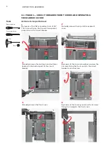
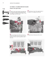
Страница 66: ...66 INSTRUCTION HANDBOOK ...

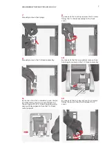
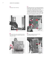
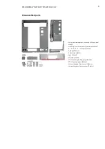
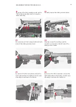
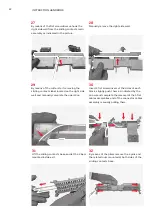
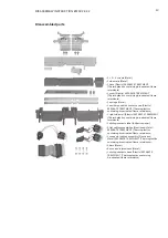
Страница 67: ...67 Disassembly instruction EMAX 2 E2 2 ...

Страница 68: ... Copyright 2022 ABB All rights reserved Specifications subject to change without notice ABB SACE A division of ABB S p A L V Breakers Via Pescaria 5 24123 Bergamo Italy Phone 39 035 395 111 Fax 39 035 395 306 433 abb it lowvoltage ...

Отзывы: