


158
Fuse failure supervision (FFRW)
&KDSWHU
6HFRQGDU\V\VWHPVXSHUYLVLRQ
)XVHIDLOXUHVXSHUYLVLRQ))5:
$SSOLFDWLRQ
Different protection functions within the REO 517 protection, control and monitoring
terminals operate on the basis of the measured voltage in the relay point. Examples are:
distance protection function, undervoltage measuring function and voltage check for
the weak infeed logic.
These functions can operate unnecessarily if a fault occurs in the secondary circuits be-
tween the voltage instrument transformers and the terminal.
It is possible to use different measures to prevent such unwanted operations. Miniature
circuit breakers in the voltage measuring circuits, located as close as possible to the
voltage instrument transformers, are one of them. Separate fuse-failure monitoring re-
lays or elements within the protection and monitoring devices are another possibilities.
These solutions are combined to get the best possible effect in the fuse failure supervi-
sion function of REx 5xx terminals.
The fuse-failure supervision function, FFRW is intended for single- and two-phase sys-
tems.
The fuse-failure supervision function integrated in the REO 517 works as follows:
•
On the basis of external binary signals from the miniature circuit breaker or from
the line disconnector. In the first case all voltage dependent functions are affected.
However, in the second case the impedance measuring function is not affected.
•
based on changes: a large change in the voltage without a corresponding large
change in the current.
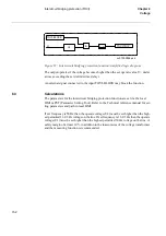
)XQFWLRQDOLW\
The current and voltage measuring elements within one of the built-in digital signal pro-
cessors continuously measure the currents and voltages in all phases and calculate:
•
The change of current
∆
I/
∆
t
•
The change of voltage
∆
U/
∆
t
comparing them with their respective set values
∆
I< and
∆
U>.
The function becomes active one and a half period after the voltage exceeds the set op-
erate value U<.
Содержание REO 517
Страница 10: ... RQWHQWV ...
Страница 16: ...6 Introduction to the application manual KDSWHU QWURGXFWLRQ ...
Страница 64: ...54 Blocking of signals during test KDSWHU RPPRQ IXQFWLRQV ...
Страница 88: ...78 Scheme communication logic ZCOM KDSWHU LQH LPSHGDQFH ...
Страница 100: ...90 Time delayed phase and residual overcurrent protection TOC1 KDSWHU XUUHQW Equation 36 Iset IsSEC I1b 100 ...
Страница 146: ...136 Unbalance protection for capacitor banks TOCC KDSWHU XUUHQW ...
Страница 166: ...156 Dead line detection DLD KDSWHU 3RZHU V VWHP VXSHUYLVLRQ ...
Страница 171: ...161 About this chapter KDSWHU RQWURO KDSWHU RQWURO ERXW WKLV FKDSWHU This chapter describes the control functions ...
Страница 293: ...283 About this chapter KDSWHU RJLF KDSWHU RJLF ERXW WKLV FKDSWHU This chapter describes the logic functions ...
Страница 378: ...368 Monitoring of DC analog measurements KDSWHU 0RQLWRULQJ ...
Страница 379: ...369 About this chapter KDSWHU 0HWHULQJ KDSWHU 0HWHULQJ ERXW WKLV FKDSWHU This chapter describes the metering functions ...
Страница 384: ...374 Pulse counter logic PC KDSWHU 0HWHULQJ ...
Страница 412: ...402 Serial communication modules SCM KDSWHU DWD FRPPXQLFDWLRQ ...
Страница 440: ...430 LED indication module KDSWHU DUGZDUH PRGXOHV ...


