

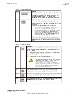
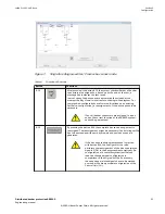


Table 7:
Function of selections
Selection
Function
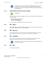
S1
One of the hardware devices can be selected from the device table
Table 8:
Function of buttons
Button
Function
B1
After all Bay Models are placed in the single-line diagram and the CU device creator
process is completed, the device labels and the associated network in the
background is automatically sorted from BU01 to BUxx → Bay Unit on the left end
side to Bay Unit on the right end side of the single-line diagram in the correct
order.
After modifications (extensions) to an existing setfile, this sequence (label) of
devices might be unsorted. By pressing the button B1, the reassignment of the
ABB-References is started from left to right side of the single-line diagram (ABB-
Reference = logical device containing label, node Id, device Id of a Bay Unit).
If the reassignment of the ABB-References is started, the node-Id
and device-Id of the Bay Units and the Central Unit may change
compared to the original setfile.
B2
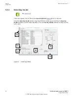
The button B2 opens the Edit device menu for the selected device.
IEC18000580-IEC18000580-1-en.vsdx
The user can fill in a device label which is
in accordance with the client system
labeling conventions. If one label is
changed, the labelling shall be worked
over for all devices.
If necessary, the hardware type of the
Bay Units can also be exchanged under
this menu item.
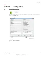
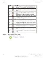
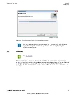
5.7
CU device creator
GUID-71CD124E-234C-4BE9-912F-AF38E2222576 v2
See
.
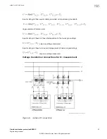
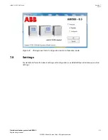
After completion of the basic setfile configuration, the single-line diagram and the bay
configuration, the design wizard of the Central Unit shall be started by the button Next.
17000043-IEC18000614-1-en.vsdx
IEC18000614 V3 EN-US
Figure 11: CU Hardware wizard
1MRK 511 452-UUS Rev. A
Section 5
Configuration
Distributed busbar protection REB500
27
Engineering manual
© 2020 Hitachi Power Grids. All rights reserved