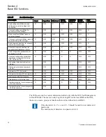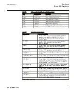
Table 16:
Self-supervision's hardware dependent internal signals
Card
Name of signal
Description
PSM
PSM-Error
Power Supply Module Error status
ADOne
ADOne-Error
Analog In Module Error status
BIM
BIM-Error
Binary In Module Error status
BOM
BOM-Error
Binary Out Module Error status
IOM
IOM-Error
In/Out Module Error status
MIM
MIM-Error
Millampere Input Module Error status
LDCM
LDCM-Error
Line Differential Communication Error status
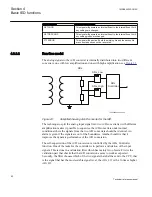
Table 17:
Explanations of internal signals
Name of signal
Reasons for activation
FAIL
This signal will be active if one or more of the following internal
signals are active; NUMFAIL, LMDERROR, WATCHDOG,
APPERROR, RTEERROR, FTFERROR, or any of the HW
dependent signals
WARNING
This signal will be active if one or more of the following internal
signals are active; RTCERROR, IEC61850ERROR,
TIMESYNCHERROR
NUMFAIL
This signal will be active if one or more of the following internal
signals are active; WATCHDOG, APPERROR, RTEERROR,
FTFERROR
NUMWARNING
This signal will be active if one or more of the following internal
signals are active; RTCERROR, IEC61850ERROR
RTCERROR
This signal will be active when there is a hardware error with the real
time clock.
TIMESYNCHERROR
This signal will be active when the source of the time synchronization
is lost, or when the time system has to make a time reset.
RTEERROR
This signal will be active if the Runtime Engine failed to do some
actions with the application threads. The actions can be loading of
settings or parameters for components, changing of setting groups,
loading or unloading of application threads.
IEC61850ERROR
This signal will be active if the IEC 61850 stack did not succeed in
some actions like reading IEC 61850 configuration, startup, for
example
WATCHDOG
This signal will be activated when the terminal has been under too
heavy load for at least 5 minutes. The operating systems background
task is used for the measurements.
LMDERROR
LON network interface, MIP/DPS, is in an unrecoverable error state.
APPERROR
This signal will be active if one or more of the application threads are
not in the state that Runtime Engine expects. The states can be
CREATED, INITIALIZED, RUNNING, for example
Table continues on next page
1MRK505222-UUS C
Section 4
Basic IED functions
81
Technical reference manual
Содержание Relion 670 series
Страница 1: ...Relion 670 series Line differential protection RED670 ANSI Technical reference manual...
Страница 2: ......
Страница 40: ...34...
Страница 50: ...44...
Страница 60: ...54...
Страница 126: ...120...
Страница 384: ...378...
Страница 496: ...490...
Страница 556: ...550...
Страница 602: ...596...
Страница 620: ...614...
Страница 794: ...788...
Страница 864: ...858...
Страница 988: ...982...
Страница 998: ...992...
Страница 1084: ...1078...
Страница 1164: ...1158...
Страница 1168: ...1162...
Страница 1170: ...1MRK002802 AB 1 670 1 2 PG ANSI V1 EN Section 21 1MRK505222 UUS C Connection diagrams 1164 Technical reference manual...
Страница 1171: ...1MRK002802 AB 2 670 1 2 PG ANSI V1 EN 1MRK505222 UUS C Section 21 Connection diagrams 1165 Technical reference manual...
Страница 1172: ...1MRK002802 AB 3 670 1 2 PG ANSI V1 EN Section 21 1MRK505222 UUS C Connection diagrams 1166 Technical reference manual...
Страница 1173: ...1MRK002802 AB 4 670 1 2 PG ANSI V1 EN 1MRK505222 UUS C Section 21 Connection diagrams 1167 Technical reference manual...
Страница 1174: ...1MRK002802 AB 5 670 1 2 ANSI V1 EN Section 21 1MRK505222 UUS C Connection diagrams 1168 Technical reference manual...
Страница 1175: ...1MRK002802 AB 6 670 1 2 ANSI V1 EN 1MRK505222 UUS C Section 21 Connection diagrams 1169 Technical reference manual...
Страница 1176: ...1MRK002802 AB 7 670 1 2 ANSI V1 EN Section 21 1MRK505222 UUS C Connection diagrams 1170 Technical reference manual...
Страница 1177: ...1MRK002802 AB 8 670 1 2 ANSI V1 EN 1MRK505222 UUS C Section 21 Connection diagrams 1171 Technical reference manual...
Страница 1178: ...1MRK002802 AB 9 670 1 2 ANSI V1 EN Section 21 1MRK505222 UUS C Connection diagrams 1172 Technical reference manual...
Страница 1179: ...1MRK002802 AB 10 670 1 2 ANSI V1 EN 1MRK505222 UUS C Section 21 Connection diagrams 1173 Technical reference manual...
Страница 1180: ...1MRK002802 AB 11 670 1 2 ANSI V1 EN Section 21 1MRK505222 UUS C Connection diagrams 1174 Technical reference manual...
Страница 1181: ...1MRK002802 AB 12 670 1 2 ANSI V1 EN 1MRK505222 UUS C Section 21 Connection diagrams 1175 Technical reference manual...
Страница 1182: ...1MRK002802 AB 13 670 1 2 ANSI V1 EN Section 21 1MRK505222 UUS C Connection diagrams 1176 Technical reference manual...
Страница 1183: ...1MRK002802 AB 14 670 1 2 ANSI V1 EN 1MRK505222 UUS C Section 21 Connection diagrams 1177 Technical reference manual...
Страница 1184: ...1MRK002802 AB 15 670 1 2 ANSI V1 EN Section 21 1MRK505222 UUS C Connection diagrams 1178 Technical reference manual...
Страница 1220: ...1214...
Страница 1230: ...1224...
Страница 1231: ...1225...

