


A-G
B-G
C-G
A-G
B-G
C-G
A-G
B-G
C-G
A-G
B-G
C-G
A- B
B-C
C-A
A- B
B-C
C-A
A- B
B-C
-A
A- B
B-C
C-A
A-G
B-G
C-G
A- B
B-C
C-A
Zone 1
Zone 2
Zone 3
Zone 4
Zone 5
C
Zone 6
A-G
B-G
C-G
A- B
B-C
C-A
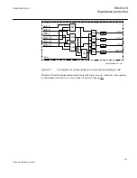
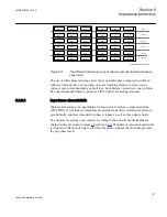
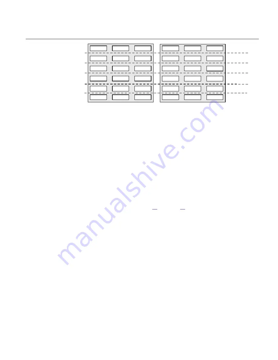
ANSI05000458-2-en.vsd
ANSI05000458 V2 EN
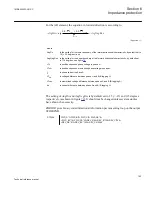
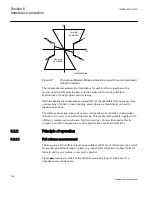
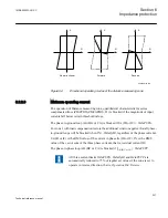
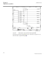
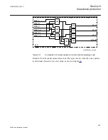
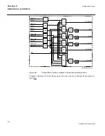
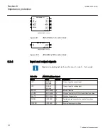
Figure 88:
The different measuring loops at phase-to-ground fault and phase-to-
phase fault
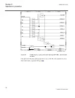
The use of full scheme technique gives faster operation time compared to switched
schemes which mostly uses a pickup of an overreaching element to select correct
voltages and current depending on fault type. Each distance protection zone performs
like one independent distance protection IED with six measuring elements.
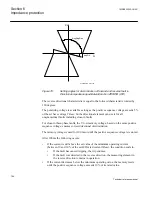
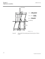
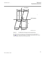
6.2.2.2
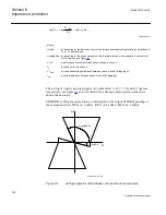
Impedance characteristic
Distance measuring zone, quadrilateral characteristic for series compensated lines
(ZMCPDIS, 21) include six impedance measuring loops; three intended for phase-to-
ground faults, and three intended for phase-to-phase as well as, three-phase faults.
The distance measuring zone operates according to the non-directional impedance
characteristics presented in figure
and figure
. The phase-to-ground characteristic
is illustrated with the full loop reach while the phase-to-phase characteristic presents
the per-phase reach.
1MRK505222-UUS C
Section 6
Impedance protection
197
Technical reference manual
Содержание Relion 670 series
Страница 1: ...Relion 670 series Line differential protection RED670 ANSI Technical reference manual...
Страница 2: ......
Страница 40: ...34...
Страница 50: ...44...
Страница 60: ...54...
Страница 126: ...120...
Страница 384: ...378...
Страница 496: ...490...
Страница 556: ...550...
Страница 602: ...596...
Страница 620: ...614...
Страница 794: ...788...
Страница 864: ...858...
Страница 988: ...982...
Страница 998: ...992...
Страница 1084: ...1078...
Страница 1164: ...1158...
Страница 1168: ...1162...
Страница 1170: ...1MRK002802 AB 1 670 1 2 PG ANSI V1 EN Section 21 1MRK505222 UUS C Connection diagrams 1164 Technical reference manual...
Страница 1171: ...1MRK002802 AB 2 670 1 2 PG ANSI V1 EN 1MRK505222 UUS C Section 21 Connection diagrams 1165 Technical reference manual...
Страница 1172: ...1MRK002802 AB 3 670 1 2 PG ANSI V1 EN Section 21 1MRK505222 UUS C Connection diagrams 1166 Technical reference manual...
Страница 1173: ...1MRK002802 AB 4 670 1 2 PG ANSI V1 EN 1MRK505222 UUS C Section 21 Connection diagrams 1167 Technical reference manual...
Страница 1174: ...1MRK002802 AB 5 670 1 2 ANSI V1 EN Section 21 1MRK505222 UUS C Connection diagrams 1168 Technical reference manual...
Страница 1175: ...1MRK002802 AB 6 670 1 2 ANSI V1 EN 1MRK505222 UUS C Section 21 Connection diagrams 1169 Technical reference manual...
Страница 1176: ...1MRK002802 AB 7 670 1 2 ANSI V1 EN Section 21 1MRK505222 UUS C Connection diagrams 1170 Technical reference manual...
Страница 1177: ...1MRK002802 AB 8 670 1 2 ANSI V1 EN 1MRK505222 UUS C Section 21 Connection diagrams 1171 Technical reference manual...
Страница 1178: ...1MRK002802 AB 9 670 1 2 ANSI V1 EN Section 21 1MRK505222 UUS C Connection diagrams 1172 Technical reference manual...
Страница 1179: ...1MRK002802 AB 10 670 1 2 ANSI V1 EN 1MRK505222 UUS C Section 21 Connection diagrams 1173 Technical reference manual...
Страница 1180: ...1MRK002802 AB 11 670 1 2 ANSI V1 EN Section 21 1MRK505222 UUS C Connection diagrams 1174 Technical reference manual...
Страница 1181: ...1MRK002802 AB 12 670 1 2 ANSI V1 EN 1MRK505222 UUS C Section 21 Connection diagrams 1175 Technical reference manual...
Страница 1182: ...1MRK002802 AB 13 670 1 2 ANSI V1 EN Section 21 1MRK505222 UUS C Connection diagrams 1176 Technical reference manual...
Страница 1183: ...1MRK002802 AB 14 670 1 2 ANSI V1 EN 1MRK505222 UUS C Section 21 Connection diagrams 1177 Technical reference manual...
Страница 1184: ...1MRK002802 AB 15 670 1 2 ANSI V1 EN Section 21 1MRK505222 UUS C Connection diagrams 1178 Technical reference manual...
Страница 1220: ...1214...
Страница 1230: ...1224...
Страница 1231: ...1225...


