


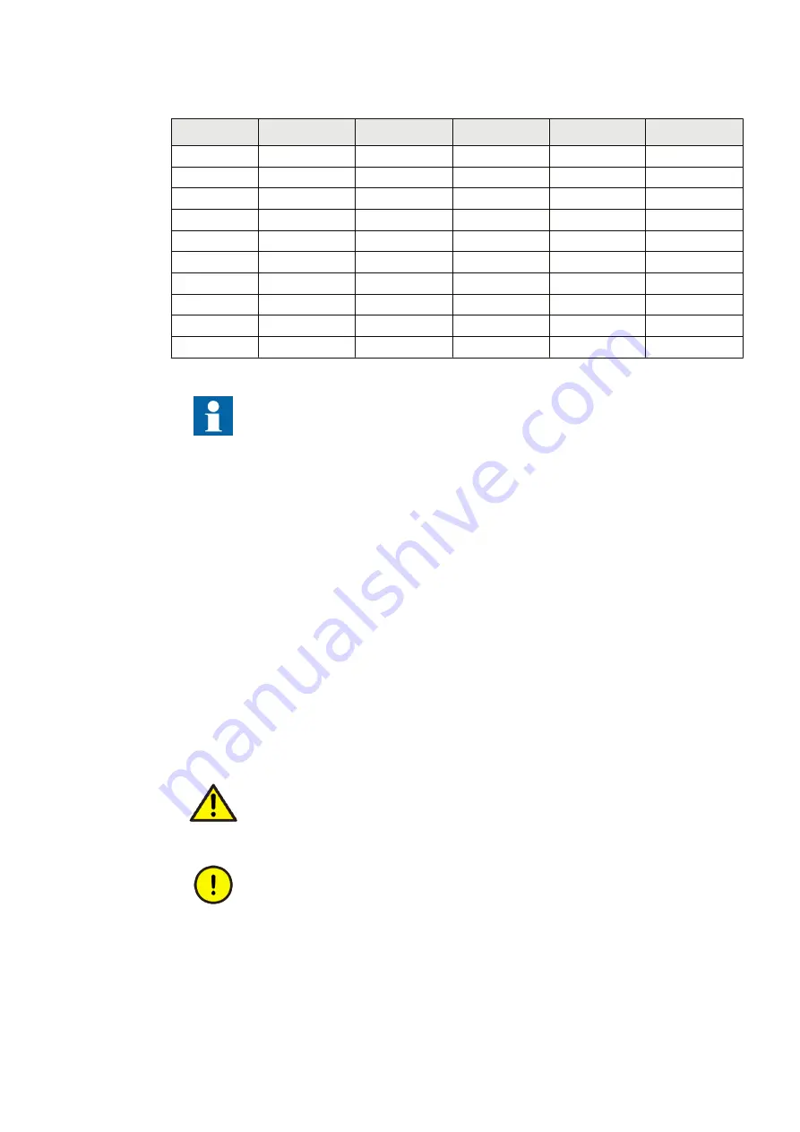
Table 3:
Analog input modules
Terminal
TRM
6I + 4U
TRM
8I + 2U
TRM
4I + 1I + 5U
AIM
6I + 4U
AIM
4I + 1I + 5U
X101-1, 2
1/5A
1/5A
1/5A
1/5A
1/5A
X101-3, 4
1/5A
1/5A
1/5A
1/5A
1/5A
X101-5, 6
1/5A
1/5A
1/5A
1/5A
1/5A
X101-7, 8
1/5A
1/5A
1/5A
1/5A
1/5A
X101-9, 10
1/5A
1/5A
0.1/0.5A
1/5A
0.1/0.5A
X102-1, 2
1/5A
1/5A
100/220V
1/5A
100/220V
X102-3, 4
100/220V
1/5A
100/220V
100/220V
100/220V
X102-5, 6
100/220V
1/5A
100/220V
100/220V
100/220V
X102-7, 8
100/220V
100/220V
100/220V
100/220V
100/220V
X102-9, 10
100/220V
100/220V
100/220V
100/220V
100/220V
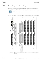
See the connection diagrams for information on the analog input module
variant included in a particular configured IED. The primary and secondary
rated values of the primary VT's and CT's are set for the analog inputs of the
IED.
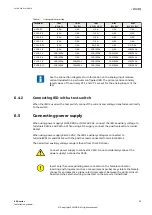
6.4.2
Connecting IED with a test switch
GUID-6752DD52-D7F6-44EE-A5D1-A2493009829C v3
When the IED is used with a test switch, connect the current and voltage transformers directly
to the switch.
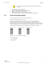
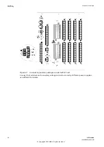
6.5
Connecting power supply
GUID-378DB1CE-5501-42DF-AC13-A360895DD943 v3.1.1
When using power supply 110-250 VDC or 100-240 VAC, connect the IED's auxiliary voltage to
terminals X410-1 and X410–3. When using a DC supply, connect the positive lead to terminal
X410–3.
When using power supply 48-125 VDC, the IED's auxiliary voltage is connected to
terminalsX410-1 and X410–2 with the positive lead connected to terminal X410–2.
The permitted auxiliary voltage range is found from the IED sticker.
Connect power supply to connector X410. Do not accidentally connect the
power supply to connector X309.
Insert only the corresponding male connector to the female connector.
Inserting anything else (such as a measurement probe) may violate the female
connector and prevent a proper electrical contact between the printed circuit
board and the external wiring connected to the screw terminal block.
1MRK 514 014-UEN A
Section 6
Connecting
650 series
33
Installation manual
© Copyright 2011 ABB. All rights reserved