background image

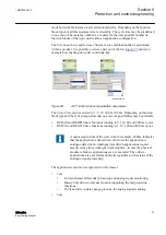
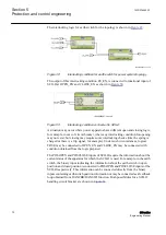
IEC09000688-1-en.vsd

IEC09000688 V1 EN

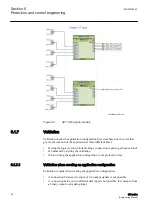
Figure 37:

Cycle time and execution order

A function block type can be defined to be a member of one or several cycle times. A
function block instance can be set only to one cycle time.

See examples for 630 series:

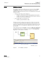
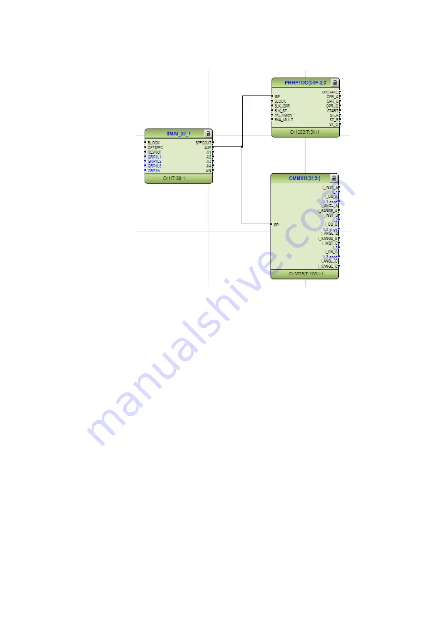
In order to have full advantage of the fast 5 ms and 3 ms cycle times all function blocks
in the signal chain need to have the same cycle time. Instantaneous protection function
running in 3 ms cycle time needs to be connected to the preprocessing SMAI_20
function block that is also running at 3 ms task cycle. In addition logic function blocks
used with these fast cycle protection functions need to have 3 ms task cycle. Same
procedure needs to be followed for each cycle time.

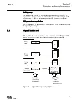
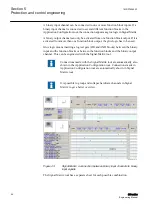
SMAI_80 function included in REF630 product offers support for higher sampling
frequency for analog inputs - 80 samples per line frequency cycle (4 kHz in 50 Hz
network). This high sampling frequency is needed for the intermittent earth fault
protection function INTRPTEF and analog group signal to it needs to be connected
from SMAI_80 FB. Other functions can also use lower sampling frequency provided
by SMAI_20 FB (20 samples per line frequency cycle).

1MRS756800 F

Section 5

Protection and control engineering

630 series

59

Engineering Manual

Содержание Relion 630 Series

Страница 1: ...RELION PROTECTION AND CONTROL 630 series Engineering Manual...

Страница 2: ......

Страница 3: ...Document ID 1MRS756800 Issued 2019 02 25 Revision F Product version 1 3 Copyright 2019 ABB All rights reserved...

Страница 4: ...bed in this document is furnished under a license and may be used copied or disclosed only in accordance with the terms of such license Trademarks ABB and Relion are registered trademarks of the ABB G...

Страница 5: ...ted and communicate data and information via a network interface which should be connected to a secure network It is the sole responsibility of the person or entity responsible for network administrat...

Страница 6: ...rning electrical equipment for use within specified voltage limits Low voltage directive 2006 95 EC This conformity is the result of tests conducted by ABB in accordance with the product standards EN...

Страница 7: ...etween PCM600 and the protection relay 22 Section 4 Setting up a project 25 PCM600 operates on projects 25 Installing Connectivity packages 25 Setting up communication between PCM600 and the IED 26 Pr...

Страница 8: ...eaker Circuit switch 76 Section 6 Local HMI engineering 79 LED and function key engineering 79 Local HMI engineering process 79 LED operation modes 84 Single line diagram engineering 89 Concept descri...

Страница 9: ...g conducting equipment for a bay 118 Mapping logical nodes 119 Creating data sets with IET600 120 Creating report control blocks with IET600 122 RCB client configuration with IET600 123 Configuring RC...

Страница 10: ...C 61850 reengineering 140 Updating DNP3 points in the Communication Management tool 141 Mapping in Graphical Display Editor 141 Updating Signal Matrix 141 Changed functions 142 Section 11 Glossary 145...

Страница 11: ...60870 5 103 IEC 61850 and DNP3 1 2 Intended audience This manual addresses system and project engineers involved in the engineering process of a project and installation and commissioning personnel w...

Страница 12: ...ure 1 The intended use of documents during the product life cycle Product series and product specific manuals can be downloaded from the ABB Web site http www abb com relion 1 3 2 Document revision hi...

Страница 13: ...use a certain function Although warning hazards are related to personal injury it is necessary to understand that under certain operational conditions operation of damaged equipment may result in deg...

Страница 14: ...1 Three phase non directional overcurrent protection high stage PHHPTOC 3I 51P 2 Three phase non directional overcurrent protection instantaneous stage PHIPTOC 3I 50P 51P Voltage dependent overcurrent...

Страница 15: ...rmal overload protection for feeder T1PTTR 3Ith F 49F Three phase thermal overload protection two time constants T2PTTR 3Ith T G 49T G Three phase thermal overload protection for motors MPTTR 3Ith M 4...

Страница 16: ...S Z GT 21GT Circuit breaker failure protection CCBRBRF 3I I0 BF 51BF 51NBF Tripping logic TRPPTRC I O 94 Multipurpose analog protection MAPGAPC MAP MAP Protection related functions Local acceleration...

Страница 17: ...VEXP Hot spot and insulation ageing rate monitoring for transformers HSARSPTR 3Ihp T 26 49HS Tap position indication TPOSSLTC TPOSM 84M Power quality Voltage variation PHQVVR PQMU PQMV Voltage unbalan...

Страница 18: ...y channels 1 16 B1RBDR BCH1 BCH1 Binary channels 17 32 B2RBDR BCH2 BCH2 Binary channels 33 48 B3RBDR BCH3 BCH3 Binary channels 49 64 B4RBDR BCH4 BCH4 Station communication GOOSE Binary receive GOOSEBI...

Страница 19: ...or the Application Configuration tool Communication management IEC 61850 station communication engineering is done using a separate tool IET600 PCM600 interacts with IET600 by importing and exporting...

Страница 20: ...ions for managing projects and organizing user rights PCM600 user management Organizing users regarding their rights profiles and passwords to use different tools and functions in the tools Defining a...

Страница 21: ...vel Station level Station Communication Station bus bay IED 1 bay IED 2 bay IED n 1 bay IED n NCC GW station IED2 PCM600 tool set HSI station IED1 GUID 414609A0 5B40 453F 83D4 4551B2894023 V1 EN Figur...

Страница 22: ...logical node in the IEC 61850 standard The mapping between the logical node data model in the device following the structure and rules in part 7 of the IEC 61850 standard and the function blocks in a...

Страница 23: ...he different steps Create plant structure and insert IED objects Write configuration to IED IEC09000623 V4 EN Figure 4 Protection relay engineering workflow The described sequence is a proposal based...

Страница 24: ...for other engineering tools within PCM600 for example for the Parameter Setting tool Parameter setting and configuration in the Parameter Setting tool Configuration parameters such as CT and VT conve...

Страница 25: ...ring The Application Configuration tool and Parameter Setting tool are used for IEC 60870 5 103 engineering After changing the parameters marked with on LHMI IEC 61850 data model user management setti...

Страница 26: ...20...

Страница 27: ...are used to create configuration structures in PCM600 The latest PCM600 and connectivity packages are backward compatible with older protection relay versions A connectivity package includes all the...

Страница 28: ...ojects Rename projects Copy and paste projects The extension of the exported project file is pcmp The files are only used for exporting and importing projects between PCM600s 3 4 Communication between...

Страница 29: ...protection relay to match the IP addresses of the physical IEDs 4 Technical keys of the IEDs in PCM600 project are configured for each protection relay to match the technical keys of the physical IEDs...

Страница 30: ...24...

Страница 31: ...to be installed on the PC A Connectivity package is managed in a separate tool called Update Manager 1 Close PCM600 2 Run the RE_630 Connectivity Package Ver n exe installer n version number 3 To ins...

Страница 32: ...IP Each IED has an Ethernet interface connector on the front and on the rear side Both Ethernet connectors can be used for communication with PCM600 When an Ethernet based station protocol is used PC...

Страница 33: ...rear port IP addresses cannot belong to the same subnet or communication will fail It is recommended to change the IP address of the front port if the front and rear port are set to the same subnet S...

Страница 34: ...Copy and paste projects An extension of the exported project file is pcmp and those files are only used for exporting and importing projects between PCM600s 4 4 1 Creating a new project 1 On the File...

Страница 35: ...pment in the substation In PCM600 it is possible to set up a hierarchical structure of five levels for the IED identification The plant structure is built up according to the project requirements PCM6...

Страница 36: ...nt structure 1 Create a new plant structure in one of the alternative ways Right click in Plant Structure and then select New Create from Template Right click in Plant Structure and then select New Ge...

Страница 37: ...The technical key is automatically generated based on the rules and type specifications of IEC 61346 and the extended definitions done for substations by a technical committee The technical key is sh...

Страница 38: ...4 6 Inserting IEDs The context menu or the Object Types view shows the available 630 series IEDs possible to insert on the bay level in the plant structure according to the installed connectivity pac...

Страница 39: ...s in offline mode or online mode from the plant structure A red color cross before the IED symbol indicates the offline mode as shown in Figure 9 IEC09000361 1 en vsd GUID 659A66EC 34BC 4B54 9EE3 148D...

Страница 40: ...t select the IED communication protocol and click Next The Communication protocol selection page is displayed IEC09000364 2 en vsd IEC09000364 V2 EN Figure 11 PCM600 Communication protocol selection w...

Страница 41: ...ext in the Configuration Wizard 6 Cross check that the IED whose IP address has been inserted has been detected online by PCM600 If the IED is not online or the IP address is not correct data cannot b...

Страница 42: ...6 V3 EN Figure 13 PCM600 IED Version detection 8 Click Scan to scan read the order code of the IED After a successful scan click Next Section 4 1MRS756800 F Setting up a project 36 630 series Engineer...

Страница 43: ...age dialog shows the summary of the IED Type Product Version IP Address of IED and Selected Order Code It is possible to cancel the insertion or confirm the configuration and do the insertion with Fin...

Страница 44: ...nfiguration from the IED to ensure that the IED object in PCM600 has the same configuration data as the physical IED The reading of IEC 61850 communication configuration is not supported when reading...

Страница 45: ...plication area for example Feeder IEDs 2 Select the IED type to be inserted Alternatively drag an IED from the Object Types view to the bay level The Configuration mode selection page opens GUID CF10F...

Страница 46: ...n page 5 Setting up an IED in the offline mode is similar as in the online mode However with the offline mode it is not necessary to type the correct IP address in the Communication port and IP addres...

Страница 47: ...18 IEC61850 communication protocol 6 Select the correct product version on the Version selection page and click Next 7 Select correct order code on the Order code selection page 1MRS756800 F Section 4...

Страница 48: ...code selection page 8 Click Next on the Setup complete page that shows the summary of the IED type version IP address and the selected order number Ensure that the order code is correct Section 4 1MR...

Страница 49: ...ssible to insert an IED from the template library to create a new IED in the plant structure Change the IP address the name and the technical key that corresponds to the physical IED after a template...

Страница 50: ...ble IEDs 3 Click the icon on the right column in the list of available templates The Template Properties dialog box opens IEC09000372 V2 EN Figure 22 PCM600 IED Template Properties 4 Delete import or...

Страница 51: ...e as pcmi files and include all information that is related to the IED object in PCM600 The pre configuration is bound to a specific hardware configuration A license update tool is needed to be run to...

Страница 52: ...ion uses functions that are not included in the license the configuration can not be written to the IED Mismatches in the license are shown in Application Configuration Functions that are not availabl...

Страница 53: ...onnected The IP address of the physical IEDs front and rear port can not be set from PCM600 but only from LHMI Via the first window of the wizard when including a new IED in a project IEC09000365 2 en...

Страница 54: ...om range A Z or a z PCM600 sets technical key values for inserted IEDs based on IEC 61850 naming conventions The default value in the IED can be replaced either with the current value in PCM600 or wit...

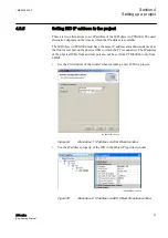
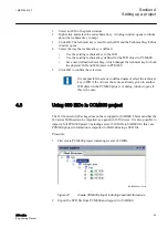
Страница 55: ...the technical key in IED if the value is the same as already given to another IED object in the PCM600 project A dialog window opens if this is the case 4 8 Using 630 IEDs in COM600 project The 630 C...

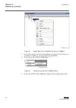
Страница 56: ...C 61850 OPC Server properties to enable the event reporting for imported IEDs 4 Create new generic IED in SAB600 project IEC09000394 1 en vsd IEC09000394 V1 EN Figure 29 Create new generic IED in SAB6...

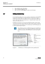
Страница 57: ...trization from COM600 Set the parameters in SAB600 1 In the Web Server Enabled box type True 2 In the Web Server IP Address box type the IP address IEC09000396 1 en vsd IEC09000396 V1 EN Figure 31 Ena...

Страница 58: ...I Write mode via the LHMI 3 To open the WHMI write the IED IP address to the address bar of the browser 4 9 1 Logging in If no users have been created with PCM600 both the default user ID and password...

Страница 59: ...0 communication protocol manual for more information Other function blocks are not mapped as logical nodes Logical gates Timers LEDs Function keys The Application Configuration tool has some basic gen...

Страница 60: ...and organized in type groups The different function block types are shown in the Object Types View Figure 34 presents an overview of the main parts that are relevant for function blocks Set user defi...

Страница 61: ...indicated by a red triangle if not connected 5 Function block name 6 Function block locked red 7 ANSI symbol 8 Inverted output 9 Hardware binary output channel 10 Hardware analog input channel 11 Use...

Страница 62: ...rted if a glue logic function block with lower execution order in the same cycle time is available Similar the output signal can only be inverted if a glue logic function block with higher execution o...

Страница 63: ...ies may be available REF630 and REM630 have functions running in 5 10 100 and 200 ms cycles RET630 and REG630 have functions running in 3 10 100 and 200 ms cycles A minus sign in front of the cycle ti...

Страница 64: ...asic logic function blocks like for example AND OR a set of combinations spread over the full range of execution orders is available This gives the possibility to select a combination which fits to th...

Страница 65: ...running at 3 ms task cycle In addition logic function blocks used with these fast cycle protection functions need to have 3 ms task cycle Same procedure needs to be followed for each cycle time SMAI_8...

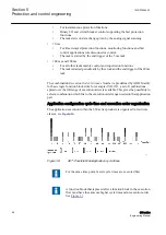
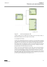
Страница 66: ...a higher execution order than the main function block in group 2 5 1 4 Configuration parameters Configuration parameters can be viewed and set with the Parameter Setting tool For example the SMAI fun...

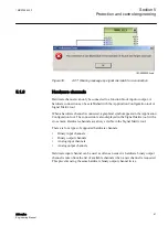
Страница 67: ...figuration tool The connection is also displayed in the Signal Matrix tool with a cross mark Hardware channels are always visible in the Signal Matrix tool There are four types of supported hardware c...

Страница 68: ...block On demand by starting the validation When writing the application configuration to the protection relay 5 1 7 1 Validation when creating an application configuration Validation is made when cre...

Страница 69: ...a cross Example unconnected hardware output Warnings do not prevent writing to the protection relay However errors must be corrected before writing the application configuration to the protection rela...

Страница 70: ...XRIO and CSV formats are supported Do not make Parameter Setting read write operation to IED when disturbance recorder is storing data since that causes PCM600 to report that the IED is offline or hav...

Страница 71: ...isible in the plant structure by expanding the setting tree 5 3 Signal Matrix tool The Signal Matrix tool is used to make cross references between the physical I O signals and function blocks and for...

Страница 72: ...cks or between the function blocks and the binary output channel This can be engineered with the Signal Matrix tool Connections made with the Signal Matrix tool are automatically also shown in the App...

Страница 73: ...ure 44 provides an overview from what places the apparatus control function receives commands Commands to an apparatus can be initiated from the Control Center CC the station HMI or the local HMI on t...

Страница 74: ...ontrol is realized by means of a number of function blocks designated LocalRemote switch LOCREM Bay control QCCBAY Switch controller GNRLCSWI Circuit breaker DAXCBR Circuit switch DAXSWI The three lat...

Страница 75: ...gurations LOCREM function has the three following binary inputs CTRLOFF LOCCTRL and REMCTRL The information from the external switch needs to be connected to LOCREM function via binary inputs Consider...

Страница 76: ...on from local or remote The connections between LOCREM and QCCBAY functions are not visible to the customer they are internally connected If LOCREM indicates that R L switch is in REMOTE mode the same...

Страница 77: ...witchyard topology Customer need to prepare the interlocking conditions logics using OR AND logics and this information is given to SCILO at OPEN_EN and CLOSE_EN inputs Let s take an example consider...

Страница 78: ...r there is a trip signal for example Under such circumstances logical TRUE may be connected to OPEN_EN and CLOSE_EN may be connected with condition obtained from the logic prepared The POSOPEN and POS...

Страница 79: ...OPEN and SCILO EN_CLOSE are connected directly to input enable open and close of GNRLCSWI EN_OPEN and GNRLCSWI EN_CLOSE as shown in Figure 52 IEC09000609 1 en vsd IEC09000609 V1 EN Figure 52 Connectio...

Страница 80: ...pparatus from the Display page and using Open Close button available on LHMI When local automation functions are used for opening or closing operation the opening and closing command from such local a...

Страница 81: ...en vsd IEC09000602 V1 EN Figure 53 Example of interaction between GNRLCSWI SYNCRSYN synchrocheck and synchronizing function and DAXCBR functions RES_EXT input deals with the reservation functionality...

Страница 82: ...ed either from LHMI or by L_SEL input output SELECTED is activated indicating the selection has been made and now waiting for the opening or closing command The blocking of execution of command if any...

Страница 83: ...ing or closing of the circuit breaker or the disconnector or earth switch is connected to EXE_OP and EXE_CL output of the DAXCBR DAXSWI function If the function is blocked to perform opening or closin...

Страница 84: ...78...

Страница 85: ...nd the required sequences IEC09000622_1_en vsd Local HMI ACT SMT Select and configure HMI function blocks PST Set function keys and LEDs END SAVE SAVE GDE ACT Create the single line diagram SAVE GUID...

Страница 86: ...make the dynamic links for the apparatus to make the dynamic links for measurements Application Configuration tool and local HMI function blocks A set of special function blocks is available for all...

Страница 87: ...les the timer tReset and tMax for the LED operation mode LatchedReset S Function block GRP1_LED1 to GRP3_LED15 The 15 LEDs on the right side of the display can indicate in total 45 alarms warnings or...

Страница 88: ...eft side of the display No execution of the function is done So the first push is used to activate the presentation only The next key push is handled as activate function and the output signal of the...

Страница 89: ...signals is done for all three signals RED YELLOW GREEN of the LED A reset of the LLEDs operates also on all three signals of the LEDs Follow S The LED illumination follows the status of the signal Th...

Страница 90: ...ed to indicate a disturbance The LEDs will stay in the last state after the disturbance run time until they are reset after a defined time The timers are set in Parameter Setting tool in the function...

Страница 91: ...pplicable See Figure 60 for the valid priority rules The LED illuminates always in steady state LED operation mode Follow F IEC08000396 vsd Steady Flash Illumination R Y G R Y G Signals LED IEC0800039...

Страница 92: ...possibilities for the operator to acknowledge The signal is already gone when acknowledged the LED turns OFF at least for this color The signal is still ON the LED stays illuminated and changes to ste...

Страница 93: ...Y G Signals LED Ack Steady Flash Illumination IEC08000399 V1 EN Figure 64 LHMI LED operation mode LatchedAck F S Prio 2 LED operation mode LatchedAck S F This operation mode operates exactly as the o...

Страница 94: ...turbance see Figure 66 The signal state after the disturbance allows a fast overview about the disturbance To get always the situation of the last occurred disturbance the LEDs are reset after a prede...

Страница 95: ...ase angles are shown as radians in the single line diagram GDE measurand symbols but in degrees in other views on the LHMI 6 2 1 Concept description to present and generate diagrams in graphical displ...

Страница 96: ...ow and sequence order Rules to handle HMI pages Several single line diagrams can be created for one bay The IED supports one bay The sequence order of the HMI pages in the Graphical Display Editor sta...

Страница 97: ...when selected Select the format and drop it in the drawing area Use the object properties to make adaptations Special symbols for dynamic text In the text pane the symbol library contains a set of spe...

Страница 98: ...raster The name and the unit of a measurement or text symbol can be changed either by double click the symbol or via the object property window Select and toggle Show Texts using the IED Fonts to get...

Страница 99: ...tions ANSI Y32 2 IEEE 315 symbol definitions Category Junction 1 Connections Busbar junction 2 Connections Earth 10 Connections Feeder end 21 Connections Current transformer 5 Measuring transformers V...

Страница 100: ...tchgear Isolator 11 Undefined 3 Switchgear Breaker 00 Middle position 4 Switchgear Breaker 01 Open 4 Switchgear Breaker 10 Closed 4 Switchgear Breaker 11 Undefined 4 Switchgear Truck 00 Middle positio...

Страница 101: ...0 Closed 27 Switchgear Isolator motor operated 11 Undefined 27 Switchgear Isolator2 00 Middle position 32 Switchgear Isolator2 01 Open 32 Switchgear Isolator2 10 Closed 32 Switchgear Isolator2 11 Unde...

Страница 102: ...Texts Indication button 11 Undefined 31 Texts 6 2 3 Bay configuration engineering A page with a single line diagram and measurements contains active living objects The object values are updated by the...

Страница 103: ...nstance numbers 10 Validate that all links are done 11 Save the complete picture 12 Repeat the steps for all pages when more than one is needed 13 Write the display configuration to IED from the GDE t...

Страница 104: ...surements VSGGIO for one bit indications for the dynamic text symbols SLGGGIO for 32 bit indications for the dynamic text symbols 1 Right click the apparatus symbol and select Select Input Signal A li...

Страница 105: ...number given in the PST tree and to the application function block in ACT Only those apparatus and measurements are shown that are configured in the application configuration program en05000611 vsd G...

Страница 106: ...ivers angles in radians a scale factor of 180 pi 57 3 shall be used to display the angle in degrees IEC10000174 vsd GUID CA49988A 9B92 4097 903C 75CEA020CBA4 V1 EN Figure 74 GDE Object properties wind...

Страница 107: ...on the demands and advantages of the IEC 61850 standard This means that there is a strict relation between the function blocks and the logical node types This relation is automatically handled by the...

Страница 108: ...e logical nodes representing the functions All signal information for commands and monitoring are available in logical nodes Whenever a function block is instantiated in the Application Configuration...

Страница 109: ...he standard only defines the IED as a receiver of the GOOSE message How the GOOSE input signals are handled must be defined in the IED application configuration The SCD file generated by the IET600 st...

Страница 110: ...l interface for the IED the following additional product manuals or knowledge of their contents is required Knowledge of the IEC 61850 engineering process as described in the IEC 61850 standard The te...

Страница 111: ...IED PCM600 3 SCD file IED 1 IED n IED 2 IED n 1 GUID 5096E041 8757 49F2 BB8D D02B6222C359 V1 EN Figure 77 IEC 61850 Signal engineering procedure flow 7 3 Exporting SCL files from PCM600 A pre conditio...

Страница 112: ...Export Private Sections and click Export to export the private sections to the SCD file A progress window shows the ongoing export of the station 7 3 2 Exporting ICD or CID files 1 Select the IED in t...

Страница 113: ...5 B39E 197A7C7A4EDB V1 EN Figure 81 IEC 61850 Export IED file Options 6 Click Export 7 4 Engineering of vertical and horizontal communication in IET600 For IEC 61850 engineering a separate system conf...

Страница 114: ...cal communication 3 4 Link the IED clients to the Report Control Blocks Up to five report clients can be configured 4 Do horizontal communication engineering 4 1 Configure GOOSE control blocks for eac...

Страница 115: ...are needed The IED of type Generic IEC 61850 IED is used to integrate these kinds of IEDs into the plant structure for example Click Ignore PCM Object Type to update the IED object s in PCM600 from t...

Страница 116: ...receiving function blocks in the application configuration 7 Write the configuration to the IED In the Plant Structure view select the IED right click and select Write to IED GUID 72BA958D 8725 4C63 A...

Страница 117: ...xample the plant structure Ignore PCM Object Type updates the IED object s in PCM600 from the IED type s in the SCD file discarding whether or not the IED type s in the SCD file matches the IED object...

Страница 118: ...ow IEC09000729 2 en vsd IEC09000729 V2 EN Figure 85 Updating the communication configuration in the IED with the configuration made in PCM600 7 7 IET600 engineering After the IED configurations are pr...

Страница 119: ...C256 4A8B BB72 D8CF0621B4F4 V1 EN Figure 86 Creating a new project in IET600 Import an SCD file exported from PCM600 Choose Import SCL File from the shortcut menu of the project object Click the Impor...

Страница 120: ...EC 61850 clients for IET600 IED SCL export from PCM600 for 630 series preconfigurations contains five default client definitions Client1 Client5 which are used by all the RCBs For example MicroSCADA a...

Страница 121: ...ched to a subnetwork 1 Click the Communication tab in the navigation pane 2 Click the Subnetworks tab in the editor pane 3 In the Subnetworks grid select the bus from the Subnetwork list to attach the...

Страница 122: ...itors It has three tabs which correspond to three different context views Substation Full substation topology and primary equipment nodes IEDs IED nodes and corresponding functionality Communication S...

Страница 123: ...lemented as tables These grid editors provide features like setting column visibility filtering sorting automatic data filling copying and pasting finding and replacing and exporting to Excel Most tab...

Страница 124: ...ides tools to draw the primary equipment and the interconnection between the equipment in the bay Also the bay equipment can be connected to the busbar to define a complete single line diagram for a v...

Страница 125: ...el LNs related to the conducting equipment are mapped first and then all the unmapped LNs are connected to the bay level LNs associated with circuit breakers are SCILO GNRLCSWI and DAXCBR and LNs asso...

Страница 126: ...g editor 7 7 6 Creating data sets with IET600 Data sets are created or modified using the Dataset editor which consists of three parts Grid for existing data sets data set creating deleting and renami...

Страница 127: ...data set or click Insert to add data items above the selected row in the data set entries list Reporting datasets can include status and measurement type of data Also configuration and setting values...

Страница 128: ...Define the LN where the RCB is to be placed preselected LD0 LLN0 is recommended and the name for the new RCB Use the field chooser to show or hide the properties For example SeqNum Entry ID and Reaso...

Страница 129: ...ent keys can be used when editing the cells PLUS SIGN asterisk or X to add an additional client to the existing ones Numbers to change the client sequence or add clients MINUS SIGN SPACEBAR or DELETE...

Страница 130: ...otherwise the automatic RCB client configuration does not work Use buttons on the RCB client editor Clear All removes all RCB clients Configure Empty copies the default client configuration of this I...

Страница 131: ...ts value ranges from 0000 to 3FFF Application appID goID is a unique GoID for each GCB in the system Recommendation is to define a device specific value and not to use the default empty value VLAN ID...

Страница 132: ...B sender it cannot be configured as a client Different keys can be used when editing the cells PLUS SIGN asterisk or X key to add an additional client to the existing ones MINUS SIGN SPACEBAR or DELET...

Страница 133: ...tion configuration to the inputs of the corresponding IEC 60870 5 103 function block 3 Set the function type and desired information number where an information number must be supplied for each IEC 60...

Страница 134: ...128...

Страница 135: ...supported Use direction icons that are located between the windows to move all signals or a set of individual signals between the windows DNP3 signal types index and default setting for classes are p...

Страница 136: ...CTVGRP Basic IED functions and SPGGIO Monitoring with the Application Configuration Tool ACT GUID E4A10C6E 40C8 4FD0 8A5A BAEFCDDC4AE3 V1 EN Figure 99 Application configuration tool To make it easier...

Страница 137: ...signal list of the master DNP point zero and one of the Binary Input Objects are used for indicating the active setting group in this case GUID 30E25076 B71E 4A97 AFD4 5BDA25E1A082 V1 EN Figure 101 S...

Страница 138: ...102 Configuring hardware channels directly to the function blocks GUID FF46FEE9 FEA6 4E29 A6D4 039148A9FB32 V1 EN Figure 103 CMT Hardware channels appearing in the Communication Management Tool 2 Righ...

Страница 139: ...text menu or press CTRL A to select all signals 5 Press the blue arrow button to insert the selected signals into the configuration 6 Press the green double arrow button to insert all signals into the...

Страница 140: ...ignals to another index sequence or select Set Index from the context menu to move one or a set of signals to another array IEC08000336 2 en vsd IEC08000336 V2 EN Figure 107 CMT Context menu in DNP3 w...

Страница 141: ...nication Management tool has a default predefined organization of classes per signal type In the master station the classes can be polled in sequences according to the demands in the project Unsolicit...

Страница 142: ...136...

Страница 143: ...backup Since the migration process is not reversible export a copy of the project for backup 1 Select Open Manage project 2 Select the project to be exported and click Export Project 10 1 2 Creating...

Страница 144: ...ons is displayed in the log window after migration The functions that are not mentioned in any of the lists have the same version in both the products Reengineering is not necessary for those function...

Страница 145: ...t indicates that the function has been replaced by another function or the migration has not been possible for other reasons If a signal has been removed it indicatesthattheparticularsignalhasanewfunc...

Страница 146: ...se signals are listed in the migration log window Export the SCD file again and redo the SCL engineering for the data attributes removed at migration The names of the signals data objects and logical...

Страница 147: ...h signals when the update of signals is finished 6 Repeat the procedure for all signal types and all configured DNP3 masters TCP 1 4 Analog input objects Binary input objects Binary output objects Cou...

Страница 148: ...ues for Operate time delay Dead line time and Cur voltage Det time and step resolution for all time settings MNSPTOC DO type corrected LREFPNDF Removal of setting Base value Sel Res Now internal minim...

Страница 149: ...mappings DRRDRE Internal change for process event clearing SELFSUPEVLIST Internal change for process event clearing MST1TCP Missing parameter obj03DefVar corrected MST2TCP Missing parameter obj03DefV...

Страница 150: ...144...

Страница 151: ...rent transformer Data attribute Defines the name format range of possible values and representation of values while being communicated Data set The content basis for reporting and logging containing r...

Страница 152: ...and modeling IED Intelligent electronic device IET600 Integrated Engineering Toolbox IID Instantiated IED description IP Internet protocol IP address A set of four numbers between 0 and 255 separated...

Страница 153: ...A Supervision control and data acquisition SCD Substation configuration description SCL XML based substation description configuration language defined by IEC 61850 SMT Signal Matrix tool in PCM600 SN...

Страница 154: ...148...

Страница 155: ...149...

Страница 156: ...BB Distribution Solutions Distribution Automation P O Box 699 FI 65101 VAASA Finland Phone 358 10 22 11 www abb com mediumvoltage www abb com relion Copyright 2019 ABB All rights reserved 1MRS756800 F...

Отзывы: