125
Time delayed undervoltage protection (TUV)
Chapter 6
Voltage
1.3
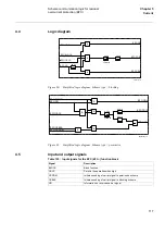
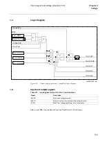
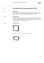
Logic diagram
Figure 65:
Undervoltage protection - simplified logic diagram
1.4
Input and output signals
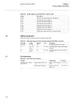
Table 131: Input signals for the TUV (TUV--) function block
Path in local HMI: ServiceReport/Functions/TimeDelayUV/FuncOutputs
TUV--TEST
Block TUV=Yes
TUV--STUL1N
TUV--STUL2N
TUV--STUL3N
&
>1
&
TEST
>1
&
&
&
xx03000076.vsd
t
TUV-BLKTR
TUV-BLOCK
TUV-VTSU
TUV-TRIP
TUV-START
TUV-STL1
TUV-STL2
TUV-STL3
Signal
Description
BLOCK
Block undervoltage function
BLKTR
Block of trip from time delayed undervoltage function
VTSU
Block from voltage transformer circuit supervision
Содержание REL 501-C1 2.5
Страница 1: ...Technical reference manual Line distance protection terminal REL 501 C1 2 5 ...
Страница 2: ......
Страница 26: ...14 Introduction to the technical reference manual Chapter 1 Introduction ...
Страница 42: ...30 Technical data Chapter 2 General ...
Страница 66: ...54 Blocking of signals during test BST Chapter 3 Common functions ...
Страница 142: ...130 Time delayed overvoltage protection TOV Chapter 6 Voltage ...
Страница 162: ...150 Autorecloser AR Chapter 9 Control ...
Страница 163: ...151 About this chapter Chapter 10 Logic Chapter 10 Logic About this chapter This chapter describes the logic functions ...
Страница 174: ...162 Event function EV Chapter 10 Logic ...
Страница 210: ...198 Serial communication Chapter 12 Data communication ...
Страница 226: ...214 Serial communication modules SCM Chapter 13 Hardware modules ...
Страница 227: ...215 Chapter 14 Diagrams Chapter 14 Diagrams This chapter contains the terminal diagrams for the terminal ...
Страница 229: ...217 Terminal diagrams Chapter 14 Diagrams 1 2 Terminal diagram REL 501 C1 Figure 86 REL 501 C1 ...
Страница 230: ...218 Terminal diagrams Chapter 14 Diagrams Figure 87 REL 501 C1 with DC switch ...
Страница 234: ...222 Terminal diagrams Chapter 14 Diagrams ...
Страница 237: ......

