119
Current reversal and weak end infeed logic for
residual overcurrent protection (EFCA)
Chapter 5
Current
5
Current reversal and weak end infeed logic for
residual overcurrent protection (EFCA)
5.1
Application
The EFCA additional communication logic is a supplement to the EFC scheme communication
logic for the residual overcurrent protection.
To achieve fast fault clearing for all earth faults on the line, the directional earth-fault protection
function can be supported with logic, that uses communication channels. REx 5xx terminals
have for this reason available additions to scheme communication logic.
If parallel lines are connected to common busbars at both terminals, overreaching permissive
communication schemes can trip unselectively due to fault current reversal. This unwanted trip-
ping affects the healthy line when a fault is cleared on the other line. This lack of security can
result in a total loss of interconnection between the two buses.To avoid this type of disturbance,
a fault current-reversal logic (transient blocking logic) can be used.
Permissive communication schemes for residual overcurrent protection, can basically operate
only when the protection in the remote terminal can detect the fault. The detection requires a suf-
ficient minimum residual fault current, out from this terminal. The fault current can be too low
due to an opened breaker or high positive and/or zero sequence source impedance behind this
terminal. To overcome these conditions, weak end infeed (WEI) echo logic is used.
5.2
Design
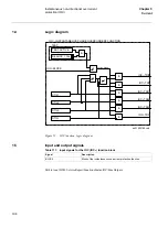
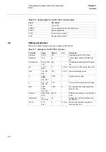
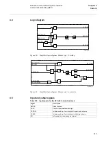
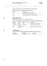
The reverse directed signal from the directional residual overcurrent function, starts the opera-
tion of a current reversal logic. The output signal, from the logic, will be activated, if the fault
has been detected in reverse direction for more than the tPickUp time set on the corresponding
timers. The tDelay timer delays the reset of the output signal. The signal blocks the operation of
the overreach permissive scheme for residual current, and thus prevents unwanted operation due
to fault current reversal.
The weak end infeed logic uses normally a forward and reverse signal from the directional re-
sidual overcurrent function. The weak end infeed logic echoes back the received permissive sig-
nal, if none of the directional measuring elements have been activated during the last 200 ms.
Further, it can be set to give signal to trip the breaker if the echo conditions are fulfilled and the
residual voltage is above the set operate value for 3U
0
>.
5.3
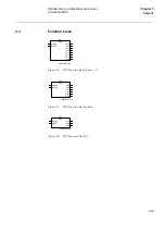
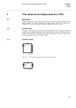
Function block
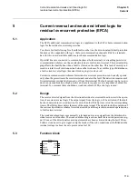
xx00000205
EFCA-
EFCA
BLOCK
IRV
IRVBLK
CBOPEN
WEIBLK
CRL
TRWEI
IRVL
ECHO
Содержание REL 501-C1 2.5
Страница 1: ...Technical reference manual Line distance protection terminal REL 501 C1 2 5 ...
Страница 2: ......
Страница 26: ...14 Introduction to the technical reference manual Chapter 1 Introduction ...
Страница 42: ...30 Technical data Chapter 2 General ...
Страница 66: ...54 Blocking of signals during test BST Chapter 3 Common functions ...
Страница 142: ...130 Time delayed overvoltage protection TOV Chapter 6 Voltage ...
Страница 162: ...150 Autorecloser AR Chapter 9 Control ...
Страница 163: ...151 About this chapter Chapter 10 Logic Chapter 10 Logic About this chapter This chapter describes the logic functions ...
Страница 174: ...162 Event function EV Chapter 10 Logic ...
Страница 210: ...198 Serial communication Chapter 12 Data communication ...
Страница 226: ...214 Serial communication modules SCM Chapter 13 Hardware modules ...
Страница 227: ...215 Chapter 14 Diagrams Chapter 14 Diagrams This chapter contains the terminal diagrams for the terminal ...
Страница 229: ...217 Terminal diagrams Chapter 14 Diagrams 1 2 Terminal diagram REL 501 C1 Figure 86 REL 501 C1 ...
Страница 230: ...218 Terminal diagrams Chapter 14 Diagrams Figure 87 REL 501 C1 with DC switch ...
Страница 234: ...222 Terminal diagrams Chapter 14 Diagrams ...
Страница 237: ......

