112
Time delayed residual overcurrent protection
(TEF)
Chapter 5
Current
3
Time delayed residual overcurrent protection
(TEF)
3.1
Application
Use the inverse and definite time delayed residual overcurrent functions in solidly earthed sys-
tems to get a sensitive and fast fault clearance of phase to earth faults.
The directional residual overcurrent protection can be used in a number of applications:
1. Main protection for phase to earth faults on the radial lines in solidly earthed sys-
tems. Selectivity is achieved by using time delayed function according to prac-
tices in the system (definite time delay or some type of inverse time
characteristic).
2. Main protection for phase to earth faults on lines in a meshed solidly earthed sys-
tem. The directional function can be used in an permissive overreach communi-
cation scheme or a blocking scheme. In this application the directional residual
overcurrent function is used together with the communication logic for residual
overcurrent protection.
3. Back-up protection for phase to earth faults for lines in solidly earthed systems.
By using the directional residual protection as back-up function, the back-up fault
clearance time can be kept relatively short together with the maintained selectiv-
ity.
4. Etc.
3.2
Functionality
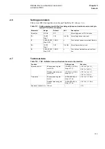
The residual overcurrent protection can be set directional. The residual voltage is used as a po-
larizing quantity. This voltage is either derived as the vectorial sum of inputs U1+U2+U3 or as
the input U4. The fault is defined to be in the forward direction if the residual current component
in the characteristic angle 65
°
(residual current lagging the reference voltage, -3U0), is larger
than the set operating current in forward direction. The same kind of measurement is performed
also in the reverse direction.
3.3
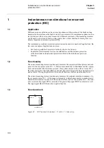
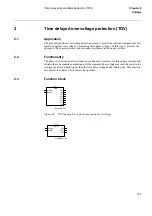
Function block
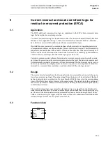
Figure 58:
Function block, directional and nondirectional
xx00000203.vsd
TEF--
TEF
BLOCK
BLKTR
BC
TRIP
TRSOTF
START
STFW
STRV
Содержание REL 501-C1 2.5
Страница 1: ...Technical reference manual Line distance protection terminal REL 501 C1 2 5 ...
Страница 2: ......
Страница 26: ...14 Introduction to the technical reference manual Chapter 1 Introduction ...
Страница 42: ...30 Technical data Chapter 2 General ...
Страница 66: ...54 Blocking of signals during test BST Chapter 3 Common functions ...
Страница 142: ...130 Time delayed overvoltage protection TOV Chapter 6 Voltage ...
Страница 162: ...150 Autorecloser AR Chapter 9 Control ...
Страница 163: ...151 About this chapter Chapter 10 Logic Chapter 10 Logic About this chapter This chapter describes the logic functions ...
Страница 174: ...162 Event function EV Chapter 10 Logic ...
Страница 210: ...198 Serial communication Chapter 12 Data communication ...
Страница 226: ...214 Serial communication modules SCM Chapter 13 Hardware modules ...
Страница 227: ...215 Chapter 14 Diagrams Chapter 14 Diagrams This chapter contains the terminal diagrams for the terminal ...
Страница 229: ...217 Terminal diagrams Chapter 14 Diagrams 1 2 Terminal diagram REL 501 C1 Figure 86 REL 501 C1 ...
Страница 230: ...218 Terminal diagrams Chapter 14 Diagrams Figure 87 REL 501 C1 with DC switch ...
Страница 234: ...222 Terminal diagrams Chapter 14 Diagrams ...
Страница 237: ......


