ABB PCS100 AVC-20 Скачать руководство пользователя страница 88

88


PCS100 AVC-20

 User Manual 


Address


Name


Access


Type


Raw Value & Scaling


1002 

Start 
Command 

Read/Write 

16-bit, 
Enum 

0 = No Action 

 Start 

1004 

Stop 
Command 

Read/Write 

16-bit, 
Enum 

0 = No Action 
1 = Stop 

1006 

Output 
Voltage 
Setpoint 

Read/Write 

16-bit, 
Signed 

Voltage (line-to-line RMS volts) = raw value 
x rated voltage / 8192 

1007 

Test Register  Read/Write 

16-bit, 
Signed 

Dummy read / write register for testing 

Table 10

-

1: PCS100 AVC

-

20 Modbus TCP User Parameters


10.3.4


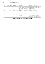
Modbus TCP Error Codes 

The following error codes may be returned by the Modbus TCP server. 


Code 

Name 

Description 

Illegal Function 

Function  code  received  in  the  query  is  not  supported  by  this 
Modbus TCP server or the query is badly formatted. 

Illegal Data Address 

The  data  address  received  in  the  query  is  not  a  valid  address  in 
the Modbus TCP server.  Specifically, the combination of address 
and number of registers is not valid. 

– 

Register not known by the PCS100 AVC-20 

– 

Register is not in Modbus TCP configuration table 

– 

Not all registers of a single parameter accessed 

– 

Register / length mismatch 

Illegal Data Value 

The value received in the query is not an  allowable  value for this 
register or the implied length is invalid. 

– 

Value out of range for parameter 

– 

Number of registers requested exceeds max. 

Slave Device Failure 

An  unrecoverable  error  occurred  while  server  attempted  to 
perform requested action. 

– 

Read/Write access violation 

– 

GDM hardware issues 

– 

Insufficient access privileges 

Slave device Busy 

The  Modbus  TCP  server  is  unable  to  process  this  command  at 
present. Retry this command again later. 

– 

GDM VCAN server busy or unavailable 

Table 10

-

2: PCS100 AVC

-

20 Modbus TCP error codes


Содержание PCS100 AVC-20

Страница 1: ... 2UCD280000E001_c PCS100 AVC 20 Active Voltage Conditioner User Manual Copyright 2015 ABB All rights reserved PCS100 AVC 20 250 kVA to 3000 kVA ...

Страница 2: ...blications available for the PCS100 AVC 20 refer to the inside cover of this publication Web links and QR code are also included The Company We are an established world force in the design and manufacturing of power electronics and power protection equipment As part of ABB a world leader in electrical technology we offer customers application expertise service and support worldwide We are committe...

Страница 3: ... Main North Road Napier New Zealand Website https new abb com ups This Document This manual contains information regarding the general functions of the PCS100 AVC 20 the component enclosures making up the PCS100 AVC 20 the user interface and control and adjustments of the PCS100 AVC 20 Usage This manual should be used during operation and adjustment of the PCS100 AVC 20 It should be referenced whe...

Страница 4: ...expertise DA Advarsel Farlig elektrisk spænding Se betjeningsvejledningen Frakobl enheden og afbryd strømforsyningen før du arbejder med denne enhed Giv agt Installation må kun foretages af personer med elektroteknisk ekspertise NO Advarsel Farlig spenning Se i bruksanvisningen Koble fra og steng av strømmen før du arbeider på denne enheten Forsiktig Montering skal kun utføres av kvalifiserte pers...

Страница 5: ... Opozorilo Nevarna napetost Glejte navodila za uporabo Pred delom na tej napravi izklopite in zaklenite električno napajanje Pozor Namestitev sme izvesti samo elektrotehnični strokovnjak FR Avertissement Tension dangereuse Consultez les consignes d utilisation Débranchez et verrouillez l alimentation électrique avant d entreprendre des travaux sur cet appareil Attention L installation doit être ef...

Страница 6: ... the PCS100 AVC 20s are high energy devices and require strict precautions to be taken CAUTION Trained Operators All operations on the PCS100 AVC 20 must only be carried out by a trained Operator familiar with the contents of this manual Hazardous conditions could arise from incorrect adjustment DANGER Hazardous Voltages An Operator must not open doors or panels marked as containing hazardous volt...

Страница 7: ...ormal operation of this product requires any protective covers to be in place and doors secured closed DANGER Personal Protection Equipment Ensure safety glasses are worn while working if any part of the unit could be energized Ensure appropriate safety footwear is worn if inserting or removing modules or components from the product ...

Страница 8: ...rnal Bypass Operation 15 3 Model Definition 17 3 1 Type Code 17 3 1 1 Rated Voltage 17 3 1 2 Power Rating 17 3 1 3 Regulation Performance 17 3 1 4 Termination Side 17 3 1 5 Options 17 3 2 Rating label 18 3 3 PCS100 AVC 20 Sizing Tool 19 3 4 PCS100 AVC 20 Model Range 20 4 Technical Specification 21 4 1 Model Range 21 4 2 Utility Input 21 4 3 Load Output 22 4 4 Performance 22 4 5 Internal Bypass 22 ...

Страница 9: ...phic display 64 8 3 8 1 Submenu A00 Display 64 8 3 8 2 Submenu B00 Network Settings 65 8 3 8 3 Submenu C00 Network Status 66 8 3 8 4 Submenu D00 Product Revisions 67 9 Event Codes and descriptions 68 10 Remote Monitoring 79 10 1 Cybersecurity 80 10 1 1 Cybersecurity Disclaimer 80 10 1 2 List of User System accounts in ABB delivery 80 10 2 Remote Web Pages 80 10 2 1 Connecting the Network Connectio...

Страница 10: ...ion 112 14 2 2 1 MCCBs 112 14 2 2 2 ACBs 113 14 2 2 3 Fuses 113 14 2 2 4 MV side protection 113 14 2 3 Calculating ARC Energy 113 14 2 4 Personal protective equipment 113 14 2 5 Keep out areas 113 14 2 6 Labeling 113 14 2 7 Restricted area 114 15 Installation Requirements 115 15 1 Maintenance Bypass 115 15 2 Floor Requirements 115 15 3 Electromagnetic Compatibility EMC 115 15 4 Location 115 15 5 C...

Страница 11: ... network where sudden changes in the grid would lead to reduced quality of supply to users 1 2 Nature of Voltage Sags One of the ways a weak network manifests itself is unstable grid voltage As a weak grid lacks the ability to withstand sudden changes the grid voltage fluctuates This affects productivity and the consistency of operations leading to a reduction in the quality of products and servic...

Страница 12: ...e with undervoltage is adaptive to load conditions Based on the loading of the unit or load power factor the PCS100 AVC 20 fully regulates undervoltage from down to 80 of the nominal voltage Detailed regulation capabilities are shown in the following table Utility Supply Problem Input Output Note Continuous undervoltage brownout 85 supply voltage 100 Load power factor 1 0 80 supply voltage 100 Loa...

Страница 13: ...kW loading 75 System kW loading 100 PCS100 AVC 20 Input Voltage 70 80 90 100 110 75 85 95 120 130 105 115 125 100 95 90 85 80 110 120 115 105 PCS100 AVC 20 Output Voltage Figure 2 2 PCS100 AVC 20 performance curve 2 1 1 How to Use Performance Curves 1 1 Determine input voltage level on the horizontal axis 2 Read regulated output voltage level on the green curve with values on left vertical axis 3 ...

Страница 14: ...delivered to the load under bypass is therefore equal to the utility voltage Bypass Inverter Rectifier PCS100 AVC 20 Input Circuit Breaker 3 phase Utility Supply 3 phase Load Injection Transformer Figure 2 3 PCS100 AVC 20 Single line diagram 2 5 Operation Detail The following diagrams show how the PCS100 AVC 20 behaves when a utility disturbance occurs and what happens if the fail safe bypass oper...

Страница 15: ...voltage Load voltage Figure 2 4 PCS100 AVC 20 Energy Flow in case of utility supply equal to nominal level 2 1 2 Internal Bypass Operation In the case of an external overload or internal fault condition the internal bypass circuit will shunt the inverter side of the injection transformer bypassing the inverter and effectively providing a direct connection from the utility supply to the output with...

Страница 16: ... PCS100 AVC 20 User Manual Utility voltage 3 phase Utility Supply 3 phase Load Bypass CLOSED PCS100 AVC 20 regulation voltage Load voltage Figure 2 5 PCS100 AVC 20 Energy Flow in case of bypass operation ...

Страница 17: ... e 380V are achieved by software settings and setting of an auxiliary transformer tapping 3 1 2 Power Rating Rated power of the system based on the number of power module pairs Each power module pair operating on rated voltage provides 500 kVA of power Note Operation at lower than the rated voltage results in less kVA per module pair Consult the rating tables for more information 3 1 3 Regulation ...

Страница 18: ... x x DMY Dummy Enclosure x x x Back to Back layout only TPx Termination Palms x x x x x I for IEC or N for NEMA PS Redundant Power Supply Unit x x x x Table 3 1 PCS100 AVC 20 available options 3 2 Rating label The information relating to specific PCS100 AVC 20 is shown on its rating label An example of a rating label is shown below Figure 3 2 PCS100 AVC 20 rating label ...

Страница 19: ...provides the PCS100 AVC Sizing Tool a Windows PC application that can be used to identify the correct PCS100 AVC 20 model required for the application Figure 3 3 PCS100 AVC 20 Sizing Tool For further information and tool availability please contact your local ABB sales office ...

Страница 20: ...B 20 x 2500 2500 1875 50 19 1 99 2 90 5B PCS100 28 400 05B 20 x 3000 3000 2250 63 24 3 99 2 108 6B PCS100 28 400 06B 20 x 380 V Application Voltage Rated apparent power kVA Rated real power kW Fault Capacity kA Losses kW Typical Efficiency Typical Airflow m3 min Frame Size Type Code To complete the Type Code Place R for right termination side or L for left termination side instead of x 380 V Utili...

Страница 21: ...age model specific 400 V application range 380 V 415 V Note Application voltage lower than the rated voltage results in power derating Consult the rating tables for more information Maximum supply voltage 130 Nominal supply frequency 50 Hz or 60 Hz Frequency tolerance 5 Hz Power system 3 phase Neutral 4 Wire Centre ground referenced TN S Overvoltage category III Fault capacity Refer to the model t...

Страница 22: ...y voltage deviation within the specification Voltage regulation accuracy 1 typical 2 max Continuous undervoltage regulation range 15 with load power factor 1 0 20 with load power factor 0 75 Continuous overvoltage regulation range 20 4 5 Internal Bypass Capacity 100 of model rating kVA Maximum overload capacity in bypass 125 for 10 minutes 150 for 1 minute 500 for 1 s 2000 for 200 ms Transfer time...

Страница 23: ...ating temperature range 0 C to 50 C Temperature derating Above 40 C derate at 2 load per C to a maximum of 50 C Operating altitude 1000 m without derating Capacity derating with altitude 1 every 100 m above 1000 m 2000 m maximum Inverter cooling Forced ventilation Transformer cooling Natural convection Humidity 95 non condensing Pollution degree rating 2 Noise 75dBA 2 m Storage temperature range 3...

Страница 24: ...g E mail 4 11 Power Quality Event Monitor Events recorded Voltage Sag RMS Voltage Surge RMS Event detection Input Voltage Sag threshold 90 of Utility voltage default setting user adjustable Surge threshold 110 of Utility voltage default setting user adjustable Accuracy Voltage 2 Duration 10 ms Remote monitoring Web Server Remote notification E mail 4 12 User Interface User interface 10 1 color tou...

Страница 25: ...ion transformer relieving load from the inverter and effectively providing a direct connection to the load The PCS100 AVC 20 is composed of two main sub assemblies Controller Enclosure Transformer Enclosure Together these sub assemblies are referred to as the PCS100 AVC 20 System The two sub assemblies on the smallest PCS100 AVC 20 frame size 1B are housed in one enclosure On larger PCS100 AVC 20 ...

Страница 26: ...houses an appropriate number of PCS100 inverter and rectifier modules module pairs for the rating of the product Each module has a unique identification number 1 16 which is displayed on the front of the module An enclosure can have a maximum of 3 module pairs For PCS100 AVC 20s requiring more than 3 pairs the controller is housed in multiple enclosures The first enclosure is called the Master Con...

Страница 27: ...CS100 AVC 20 rectifier diagram 5 1 2 PCS100 Inverter Module The PCS100 Inverter Modules are IGBT based modules that can deliver 150 A continuously Due to the technology used the PCS100 AVC 20 can respond within milliseconds to power disturbance events with precise control over the compensating voltage Based on state of the art IGBT technology and with integrated sine filters and RFI filters invert...

Страница 28: ...mless shunting of the inverter without impact on the load 5 1 4 Auxiliary Master Module The Auxiliary Master Module controls the overall system operation from a central point It coordinates the function of the slave modules The master controls the operating state of the system and combines the measurements and feedback from the input and output slaves into a single data set It also identifies sign...

Страница 29: ...n this product including printed circuit boards operate at lethal voltages DO NOT TOUCH components or connections that have voltage present The Transformer Enclosure houses the injection transformer and auxiliary circuit breaker Customer supply and load connection terminals are located in the Transformer Enclosure 5 2 1 Injection Transformer The injection transformer is connected in series with th...

Страница 30: ...n and the control panel consists of a Start I Stop O Reset button allowing local control of the product The Status Bar displays the current product status and any warning or fault condition that may be present Table 6 1 describes general features of GDM and Figure 6 1 displays Status page of GDM Feature GDM Display resolution 1024 x 600 pixels Display size 10 1 Color graphic display yes Touch sens...

Страница 31: ...s Bar Page selected in Navigation Panel Figure 6 1 PCS100 AVC 20 GDM showing the Status page 6 1 1 Navigation Panel The navigation buttons are displayed at all times Press the navigation button on the Navigation Control panel to access to the following 5 pages ...

Страница 32: ...CS100 AVC 20 User Manual 1 Status Page Navigation Buttons 2 Event Log Page 3 Product Page Press the Navigation buttons access the required page 4 Menu Page 5 Summary Page Figure 6 2 PCS100 AVC 20 GDM pages ...

Страница 33: ...0 in RUN status is shown on Figure 6 3 Status page of PCS100 AVC 20 in bypass mode is shown on Figure 6 4 Figure 6 4 GDM Status Page in bypass Status Bar RMS Voltages 𝑉1 2 𝑉𝐿1 𝑉𝐿2 𝑉2 3 𝑉𝐿2 𝑉𝐿3 𝑉3 1 𝑉𝐿3 𝑉𝐿1 Load current of product rating average phase current phase rating x 100 Apparent power rating Real power rating RMS Voltages 𝑉1 2 𝑉𝐿1 𝑉𝐿2 𝑉2 3 𝑉𝐿2 𝑉𝐿3 𝑉3 1 𝑉𝐿3 𝑉𝐿1 Frequency indicating phase rot...

Страница 34: ... found in the event log Refer Table 9 2 for a complete event description 3 Yellow Warning Bar will be displayed if any warning condition exists Note The Status Bar will only display the most recent event or what is considered the most important event Touch the Status Bar and a list of all faults and warnings presently active will be displayed Note Rectifier and inverter module warning events are n...

Страница 35: ...ter side of the injection transformer bypassing the inverter providing a direct utility supply to the output without interrupting the load This mode is entered from either a local or remote stop command from the user or a reset from a fault condition To transition to RUN operation either a local or remote start command is required The control electronics are on The power electronics are off BYPASS...

Страница 36: ...th the current fault code The fault will also be reported as an event in the system event log Examples of Fault conditions include inverter transistor de saturation sustained over temperature or over current conditions communications lost between modules in the system Some Fault conditions such as de saturation conditions cannot be reset until after a cooling period has expired STARTING Yellow The...

Страница 37: ...tronics Power Electronics AVC Bypass switch ON OFF CLOSED SCRs only AVC will correct PQ Events Reset AUTO START AUTO BYPASS END AUTO BYPASS POWER DOWN RESET LOCAL RESET REMOTE STOP LOCAL STOP REMOTE STOP LOCAL STOP REMOTE AUTO BAYPASS AUTO BAYPASS END START LOCAL START REMOTE START AUTO POWER UP and AUTO START POWER UP and AUTO STOP AUTO STOP A status is a continuing condition such as a run condit...

Страница 38: ...GDM event log page shown in Figure 6 7 Figure 6 8 Power Quality Event Log Page Accessing the pages of either of the event logs uploads the most recent event records at the top Each page shows five event records referenced by the date and time The records of both types of event logs can be scrolled through using the up 1 down 1 up 10 and down 10 arrow keys at the bottom of the page The page number ...

Страница 39: ...column shows a description of any Fault Warning or Auto Bypass See Table 9 2 for a full list of the event descriptions Table 6 3 Event Log columns Event Type Description Start Local Local Start Command Stop Local Local Stop Command Reset Local Local Reset Command Start Remote Remote Start Command This includes Modbus Stop Remote Remote Stop Command This includes Modbus Reset Remote Remote Reset Co...

Страница 40: ... details Duration The time between event start and event end in milliseconds Input Voltages Low voltage minimum line to line voltage over duration of event High voltage maximum line to line voltage over duration of event Output Voltages Low voltage minimum line to line voltage over duration of event High voltage maximum line to line voltage over duration of event Table 6 6 Power Quality Event info...

Страница 41: ...ended description of the event The Recommended Action field is only visible when logged into the GDM at the Tech level as it is primarily provided to aid trained ABB service agents resolve the fault Both the Description and Recommended Action fields are also presented in the Table 9 2 PCS100 AVC 20 Event codes and descriptions Figure 6 9 Additional event information 6 1 5 Product Page The product ...

Страница 42: ...d total hours on powered up Network Settings Ethernet network parameters Entered in Menu GDM B00 Network Settings Table 6 8 Power Quality Event types 6 1 6 Menu Page The menu provides access to the PCS100 AVC 20 and GDM parameters for viewing and or adjustment It is organized into menus and sub menus which contain the parameters Each folder and parameter are indexed by three characters to the left...

Страница 43: ...Display Boards The rectifier and inverter modules contain their own display boards which contain the RUN and OK LEDS as well as 2 x 7 segment LED displays The 7 segment displays show the individual module identification number 1 32 however if there is an error condition they will flash alternately every 500 ms the module identification number and an error code On start up they will show L0 and L1 ...

Страница 44: ...alid module configuration or invalid module parameter s E3 and module number FLASH 50 duty 1sec period Communications error rE and module number FLASH 50 duty 1sec period The module is running and it has been configured as rectifier input This is displayed for about 2 minutes after configuration L1 is completed Ou and module number FLASH 50 duty 1sec period The module is running and it has been co...

Страница 45: ...Control 7 1 1 GDM Control The Start I Stop O Reset button in the Navigation Control Panel allows GDM control of the PCS100 AVC 20 When the PCS100 AVC 20 is stopped Bypass a green Start I button will show and when running RUN a red Stop button will show Pressing the Start I Stop Reset button followed by YES in the following confirmation screen will cause that action to be taken Figure 7 1 GDM Statu...

Страница 46: ...ansition to Bypass Off in approx 1sec Stop Button Reset the PCS100 AVC 20 Figure 7 4 Reset button The Reset button is visible when the PCS100 AVC 20 status is Fault Press the Reset button and press Yes at the confirmation screen to reset a fault Reset Button Start Inhibit Figure 7 5 Start Inhibit button The Inhibit button is visible when the Inhibit switch or the remote stop input is closed The PC...

Страница 47: ...tion The PCS100 AVC 20 is configured for GDM control by default in the factory i e Stop Reset Inhibit input is linked out and Stop Enable switch is wired in series as shown on Figure 11 3 Customer Terminals for Remote Control and Monitoring of PCS100 AVC 20 The start status will be retained through a power down cycle and the PCS100 AVC 20 will return to the previous operation after the next power ...

Страница 48: ...Standard PCS100 AVC 20 only allows adjustment of the output voltage via the GDM Manual or Modbus Remote control via an analogue input is only available with the optional Extended I O board Therefore parameters relating to the Extended I O board are not described in this manual ...

Страница 49: ...ter will present the edit menu screen For numeric values this will show a keypad and for non numeric values this will show the options for that item Press Apply to accept the adjustment or Cancel to revert to the previously stored value The GDM remembers the previous menu page and returns there when the user next accesses the menu The GDM remembers the previous menu page and returns there when the...

Страница 50: ...log out of that menu 8 2 GDM Menu Index Table Menu number name Parameter number name Page Language Access to language selection page 45 0 General 00 Password 46 01 Date_andTime 02 Customer_Name 03 Plant_Name 04 Site_Name 05 System_Reboot 06 Reset_PowerQuality 07 Sys_SW_Version 08 Set_Parameter 09 Show_Faults 0A Color_Theme 1 System_Electrical 10 System_Current 48 11 Rectifier_Voltage 12 Transforme...

Страница 51: ...34 SCM_Product 35 SCM_Revision 36 CGI_Revision 37 Modbus_Revision 38 NTP_Revision 39 Email_Revision Menu number name Parameter number name Page 6 References 60 V_Setpoint 600 V_Set_Manual 51 601 V_Set_Source 602 V_Analog_Gain 603 V_Analog_Offset 604 V_Rate_Limit 61 Thermal_Roll_Off 610 Enable 611 Thermal_Set_Point 612 Rate_Limit ...

Страница 52: ...rite Enable 74 NTP_Status 75 NTP_Server 76 NTP_Time Zone 77 E mail_Service 770 SMTP_Server 771 E mail_Status 772 Status_Log 773 From_Address 774 Cutomer_note_1 775 Cutomer_note_2 777 Password 778 PQ_Events 7780 Email_Address 7782 Force_E mail 7783 Enable 779 System_Events 7790 Email_Address 7791 Trigger Type 7792 Force_E mail 7793 Enable 77A Service_Log 77A0 Email_Address 77A1 Force_E mail 77A2 En...

Страница 53: ... C13 Actual IP mask C16 Ethernet Status GDM D00 Product Revision D11 GDMIB boot product D21 GDM revision 56 D12 GDMIB boot revision D31 Vcanserver name D13 GDMIB product D32 Vcanserver revision D14 GDMIB revision Table 8 1 GDM Menu Index Table Note Menus 4 Analog I O and 5 Digital I O shown in GDM Menu Page Figure 8 1 are related to optional Extended I O board and are not used with standard PCS100...

Страница 54: ...rained Operator familiar with the contents of this manual Hazardous conditions could arise from incorrect adjustment 8 3 1 Menu Language The Menu Language enables the user to select GDM operating language Following languages are available English French Italian Malaysian Turkish Russian German Vietnamese Spanish Simplified Chinese Japanese Traditional Chinese Swedish Indonesian Portuguese Arabic K...

Страница 55: ...oaded event log Access Operator Parameter 05 System Reboot Function Restarts all functions within two minutes Access Operator Range True False Setting Up Select True to reboot the PCS100 AVC 20 The parameter will automatically set back to False once the PCS100 AVC 20 has rebooted Event 209 will be displayed in the event log Parameter 06 Reset Power Quality Function Clears the power quality events ...

Страница 56: ...an also be accessed via the remote web pages see section 10 2 6 2 Note The code must be entered exactly Take care when emailing such codes Different characters look the same in some fonts E g the lower case letter L looks the same as the numeral one in Times New Roman Font The Arial Font is OK Parameter 09 Show Faults Function Shows all the faults and warnings presently active Access Continuous No...

Страница 57: ...nput Default Top Input Setting Up Preset in the factory Note Top Input utility supply input to top Bottom Input utility supply input to bottom Changing this setting alone does not change the transformer configuration Wiring changes are also required Parameter 13 Supply Voltage Function Adjusts the PCS100 AVC 20 working voltage Access Tech Range 0 00 V to 1599 95 V Default Nameplate rating of PCS10...

Страница 58: ...oning and testing Note This menu is only visible with Tech login Parameter 20 Config Check Mode Function Provides a check of the phasing of the supply cables Access Tech Range True False Setting Up When this parameter is set to True the output regulation voltages will be V1 100 V2 105 and V3 110 of the parameter 13 Supply Voltage setting Note This check should be performed during commissioning See...

Страница 59: ...olatile value Always Auto Start Auto start using non volatile value Recommended Default No Auto Start Table 8 4 Menu 2 Commissioning Parameters 8 3 5 Menu 3 Product Revision 3 Product Revision The menu contains displays various PCS100 AVC 20 software numbers and revisions Parameter 30 System Product Function Displays the product main software number Note For PCS100 AVC 20 this is 7300 Parameter 31...

Страница 60: ...VC 20 Access Tech Range 0 to 250 Default Nameplate rating of PCS100 AVC 20 Setting Up Set to nominal supply voltage 10 RMS Note Typically this parameter is set to the same value as 13 Supply Voltage If set too close to 15 Sag Threshold or 16 Surge Threshold spurious sag surge events may be recorded in the event log Parameter 601 V Set Source Function Sets the source of output voltage setting Acces...

Страница 61: ...me Protocol client service Access Read Only Range Running clock updated if the NTP server connection is successful Invalid Server Name if no NTP server IP address has been set Server connection failed if no response from the NTP server was received Note Wait at least 30 seconds after setting the NTP server IP address parameter 75 NTP Server before refreshing menu 7 GDM Services The NTP Status fiel...

Страница 62: ...ing Note After a software upgrade the PCS100 AVC 20 needs to be rebooted twice to initialize the Modbus Parameter 731 Date Write Enable Function Controls write access to the Modbus date time register id 100 Access Tech Range True of False Default is False Note To allow Modbus writes to the system time this needs to be set to true Parameter 732 Control Write Enable Function Control write access to ...

Страница 63: ...ice An important status event key to the operation of the service Error This indicates an important failure that should not normally occur Access Operator Parameter 773 From Address Function Sets the Email address to send power quality and system event notifications to customer Access Operator Setting Up Any valid email address that the email server will except Parameter 774 Customer_note_1 Functi...

Страница 64: ...Enable When set to true this enables PQ event email notifications to be sent to the operator Parameter 77A Service Log Function Creates a service log email that is sent out on the 1st of every month This is setup in the factory 8 3 8 Menu Graphic display 8 3 8 1 Submenu A00 Display A00 Display The menu contains parameters to setup the graphic display module Name A31 GDM Control Enable Function Ena...

Страница 65: ...ired Parameter B15 Apply Settings must be set to TRUE to save this setting Name B12 Static IP address Function Configures the GDM Static IP address Range where 1 to 255 Access Operator Setting Up Parameter B15 Apply Settings must be set to TRUE to save this setting See section 10 2 for further setting up instructions Name B13 Static IP mask Function Configures the GDM Static IP mask Range where 1 ...

Страница 66: ...e C13 Actual IP mask Function Displays the actual IP mask Range where 1 to 255 Access Read Only Note Useful for debugging network connection problems Name C14 Actual IP gateway Function Displays the actual IP gateway Range where 1 to 255 Access Read Only Note Useful for debugging network connection problems Name C15 MAC address Function Displays the product s MAC address Range Access Read Only Not...

Страница 67: ...visions for the GDM Name D00 Product Revision Function Product revision information about the GDM Range D11 GDMIB Boot Product D12 GDMIB Boot Revision D13 GDMIB Product D14 GDMIB Revision D21 GDM Revision D31 Vcanserver name should be main_vcan_server D32 Vcanserver revision Access Read Only Table 8 11 Submenu D00 Product Revision ...

Страница 68: ...ly be carried out by a trained Operator familiar with the contents of this manual Hazardous conditions could arise from incorrect adjustment Abbreviation Description F Fault A fault has occurred and the PCS100 AVC 20 is in Bypass The PCS100 AVC 20 cannot be started until the fault is removed AB Auto bypass The PCS100 AVC 20 has automatically gone into auto bypass to protect itself When the conditi...

Страница 69: ...g is not resolved contact your ABB Service Agent to have the auxiliary module replaced 5 R I F Interlock Error Two of the IGBTs Insulated Gate Bipolar Transistor from the same bridge are activated Note Only one should activate at any one time Replace the faulty module 6 M R I F SPI Watchdog Error There is an SPI Serial Peripheral Interface Bus watchdog error Ensure all communication cables are con...

Страница 70: ...ontact your ABB Service Agent to have the cables replaced 18 M R I W Control Loop Timing Sustainable internal condition Control Loop processing result late Press Reset If the warning is not resolved power down and restart 19 M R I F Internal Error There was an internal error Press Reset If the fault is not resolved power down and restart 20 M R I W Stack Level Warning DSP stack has reached 75 thre...

Страница 71: ...s indicated by bypass manager Contact your ABB Service Agent to have the fault resolved 33 I F Bypass Contactor Forced Bypass SCRs enabled too long before bypass contactor detected in hardware and contactor forced closed Replace the faulty module 34 I F SCR On Timeout Bypass SCRs on too long when contactor remains open in AUTO BYPASS mode Replace the faulty module 35 I F SCR Not Off Timeout Bypass...

Страница 72: ...or rectifier Ensure all communication cables are connected and not damaged If damaged contact your ABB Service Agent to have the cables replaced If there is no damage and the fault is not resolved power down and restart 45 M F Unexpected Bypass Bypass activated for unknown reason Bypass activation not reported to the master Contact your ABB Service Agent to have the fault resolved 46 M W Inverter ...

Страница 73: ...e operating Ensure the ambient temperature is not too high 56 R I AB Heatsink Hot The inverter s or rectifier s heat sink is too hot Note A sensor is mounted on the heat sink Ensure all module fans are operating Ensure the ambient temperature is not too high 57 R I F Heatsink Over Temp The inverter s or rectifier s heat sink is too hot Note A sensor is mounted on the heat sink Ensure all module fa...

Страница 74: ...mbient temperature is not too high 65 I AB Bypass Over Temp Long duration bypass over temperature detected None 66 M W Transformer Hot Transformer is too hot Note The temperature is detected by a thermistor in transformer winding Ensure all module fans are operating Ensure the ambient temperature is not too high 67 M R I W VCAN Warning There is sustainable interference in the module communications...

Страница 75: ...e has been replaced The replacement s number was not recognized If a module has been replaced check the module ID number is set to the same as the replaced module 78 M F Module Number Mismatch Number of rectifier and inverter modules is unequal Ensure module IDs are set correctly Call service agent 79 R I W Module Display Warning There are sustainable communication errors between the module displa...

Страница 76: ...ctifier or Inverter Check ambient temperature 91 R I AB Enclosure Cold Rectifier or Inverter enclosure sensor error or too cold Repair the sensors if broken 108 R F RFI Lead Misconfigura tion The RFI configuration in the power modules does not match the Master map Check the part numbers of the power modules are correct for this machine 109 R I F Protection Message Error Protection Message Error Ch...

Страница 77: ...ceived by master mux I O lines Info only 216 System Info Modbus A Mode change command has been received by a Modbus connected device Info only 217 System Info Factory webpage A Mode change command has been received by the internal factory web pages Info only 218 System Info Remote webpage A Mode change command has been received by the remote user web pages info only 219 System Info Command Line A ...

Страница 78: ...0E430 PCS100 SCM Diagnostics 332 M W Master Reset The Master has performed a software reset Info only Caused by a software lock up or system reboot 404 R I F IGBT Gate drive Failure IGBT desaturation detected without the IGBT being switched Power down and restart If the fault is not resolved contact your ABB Service Agent to have relevant module replaced Table 9 2 PCS100 AVC 20 Event codes and des...

Страница 79: ...Web Pages Remote Web Pages are a set of web pages that are similar in format to the standard GDM and accessed through the integrated web server via the GDM Ethernet connection Through this interface the users can remotely access the status and operating parameters Viewing and downloading of event history and service logs is also available Access is via the Ethernet port of the GDM and web pages ca...

Страница 80: ... and or theft of data or information 10 1 2 List of User System accounts in ABB delivery Linux root account is only available as a service account used with SSH SSH port is disabled by default however it can be enabled through parameter settings 10 2 Remote Web Pages The Graphical Display Module contains a set of web pages that are similar in format to the standard GDM pages described in section 6...

Страница 81: ... on the bottom of the GDM using an Ethernet cable Figure 10 3 GDM Ethernet connector Connecting a GDM directly to a computer using an Ethernet cable Figure 10 4 GDM Ethernet connection You can connect one or more PCS100 AVC 20 GDMs to a network using a Ethernet switch or hub and ethernet cables Figure 10 5 Multiple GDM connections ...

Страница 82: ...ss as configured in Submenu B00 Network Settings See Section 8 3 8 2 in the address field of your PC web browser Use the format http where is the IP address of the GDM 10 2 4 Remote Web Pages Language Selection Remote Web Pages enables the users to select different language for each remote client List of available languages is shown in Section 8 3 1 Menu Language To select Remote Web Pages languag...

Страница 83: ...ges does not change the unit s GDM language 10 2 5 Viewing and Downloading the Event Log Viewing and downloading of the event log is done by the Event Log Page Figure 10 8 shows a typical remote web pages event log The number of lines per page and the range of events being view can be selected Additionally the user is able to download the event log to PC The last 100 1000 5000 or All events can be...

Страница 84: ... AVC 20 Remote Web Pages Event log The downloaded event log is in csv format and can be opened using Microsoft Excel Each event is displayed on one line See section 6 1 4 1 for a full description of the event log 10 2 6 Service Page Figure 10 9 Remote Web Pages Service Page The Service Page has following three functions ...

Страница 85: ...et Parameter 10 3 Modbus TCP Modbus TCP connection is provided with PCS100 AVC 20s fitted with the GDM user interface Connection is via an Ethernet cable to the Ethernet port on the bottom of the GDM Read Only access is available to the parameters in Table 10 1 PCS100 AVC 20 Modbus TCP User Parameters Modbus protocol is an open messaging structure developed by Modicon in 1979 used to establish mas...

Страница 86: ...ne to line RMS volts raw value e g raw value 480 Voltage 480V 5 Rated Frequency Read Only 16 bit Signed Frequency Hz raw value 32 e g raw value 1920 Frequency 60Hz 6 Rated Current Read Only 16 bit Signed Current RMS Amps raw value e g raw value 500 Current 500A 7 Input Voltage V1 V2 Read Only 16 bit Signed Voltage line to line RMS volts raw value x 13 Supply Voltage 8192 e g raw value 7782 rated v...

Страница 87: ...unsigned 0 10 29 PQ sag count Read Only 16 bit unsigned 10 20 30 PQ sag count Read Only 16 bit unsigned 20 30 31 PQ sag count Read Only 16 bit unsigned 30 40 32 PQ sag count Read Only 16 bit unsigned 40 50 33 PQ sag count Read Only 16 bit unsigned 50 60 34 PQ sag count Read Only 16 bit unsigned 60 70 35 PQ sag count Read Only 16 bit unsigned 70 80 36 PQ sag count Read Only 16 bit unsigned 80 90 37...

Страница 88: ...he data address received in the query is not a valid address in the Modbus TCP server Specifically the combination of address and number of registers is not valid Register not known by the PCS100 AVC 20 Register is not in Modbus TCP configuration table Not all registers of a single parameter accessed Register length mismatch 3 Illegal Data Value The value received in the query is not an allowable ...

Страница 89: ...le on the local network and does not support authentication The GDM needs to be configured for the local network refer to Sections 10 2 1 10 2 2 for configuration instructions A minimum of operator access is required to configure the ENS via the GDM Menu The email server should be set up as described below From the GDM menu select 7 GDM Services and then select 77 Email Service Select 770 SMTP Ser...

Страница 90: ...p Instructions Select the menu 7780 Email address and enter the destination email address for the notification to be sent to Select the menu 7783 Enable and set it to true 10 4 2 4 Testing Set Up To test the notification service select the menu 7782 Force Email the set to true This will attempt to send out an email using the email server settings and the email address entered in 7780 Email address...

Страница 91: ...ant Name Site 1 Site Information Note AVC connected to Production Line 75 Note Feeder 12 O G Product type PCS100 AVC 20 Model Product Rated voltage 480 00V Product Information Product Rated Power 1000kVA Date 2015 09 21 Date and Time Time 10 49 38 27 Input voltage V1 80 Input voltage V2 82 Utility sag at input to PCS100 AVC 20 Input voltage V3 87 Output voltage V1 100 Output voltage V2 100 PCS100 ...

Страница 92: ...fications to be sent to Select the menu 7791 Trigger Type and select desired event type to trigger the email The three event types are Trigger notification on Fault Trigger notification on Warning Trigger notification on Power Quality Note It is possible to select any or all of the event type options Select the menu 7793 Enable and set it to true 10 4 3 2 Testing To test the System event email ser...

Страница 93: ...015 09 18 16 30 13 91 system fault 70 inverter lost 2015 09 18 16 30 13 34 inverter 1 fault 2 desat 2015 09 18 16 30 13 25 inverter 1 warning 4 lvdc psu voltage low 2015 09 18 16 24 39 61 sag end running 200 ms 80 75 80 100 100 100 2015 09 18 16 24 39 61 sag end running 200ms 79 76 80 100 100 100 Note The table lists the System and PQ events The event that triggers the email is highlighted in bold...

Страница 94: ...ce the Service Log Email Notification has been enabled it can be tested by selecting the menu 77A1 Force Email and setting it to true This will attempt to send out an email using the email server settings and the email address entered in 77A0 Email address Note The service log can take up to an hour to generate 10 4 5 Email Service Status Log The 722 Status Log screen can be viewed to see the stat...

Страница 95: ...arate Transformer Enclosure Refer to section 17 6 for termination details in different frame sizes If it is required that the utility supply is connected Bottom Input to the bottom transformer terminations then the power cables which connect the Auxiliary Circuit Breaker to the transformer top terminations must be moved to the transformer bottom terminations When utility supply cables are connecte...

Страница 96: ...G 250 VAC 30 VDC 1 A FAULT 250 VAC 30 VDC 1 A TX ALARM 24 VAC VDC 1 A START 0 V STOP RESET INHIBIT LOOP 1 2 3 4 5 6 7 8 9 10 11 12 13 14 15 16 NC NC Inhibit switch Located inside inverter cabinet door fitted at factory PCS100 AVC 20 200º C Customer Monitoring and Alarm Systems Remote Control Figure 11 3 Customer Terminals for Remote Control and Monitoring of PCS100 AVC 20 Terminal Number Descripti...

Страница 97: ... condition present temperature or overload warnings and during power up FAULT Not active if FAULT or PCS100 AVC 20 is powered down Table 11 3 PCS100 AVC 20 relay outputs 10 Isolated thermal switch 24 VAC 24 VDC 1 A NC Transformer overtemperature information The transformer is overheating if this circuit opens This circuit must be monitored and action taken to reduce the temperature of the transfor...

Страница 98: ...r remote control failure this switch can be used to stop the PCS100 AVC 20 operating and put it into BYPASS mode by setting to STOP This will inhibit PCS100 AVC 20 from starting This switch is wired in series with the remote inhibit input above Returning this switch to Enable will enable the controller but not start it A local or remote start is needed to bring the system out of BYPASS ...

Страница 99: ...nformation can be found in the product manuals and detailed maintenance instructions For more information consult ABB Service NZ powerconditioningservice abb com Legend R Replacement of component I Inspection visual inspection correction and replacement if needed S On Site work tests measurements etc Recommended maintenance actions Activity Period Cooling Air ducts I 1 year All fans I 1 year Conne...

Страница 100: ...xiliary module power supply systems built before 31 7 2017 R R Auxiliary module power supply systems built after 31 7 2017 R SCM board SCM rev F and earlier systems built before 18 6 2015 R SCM board battery SCM rev G and later systems built after 18 6 2015 R If for any reason there is the need to replace a module from year 8 onward we recommend that the opportunity is taken to replace the CAN bus...

Страница 101: ...ntroller Enclosure Weight Transformer Enclosure Weight 1B 2154x809x804 mm 1155 2B 2154x809x804 mm 2154x809x804 mm 581 kg 1520 kg 3B 2154x809x804 mm 2154x809x1204 mm 714 kg 2380 kg 4B 2154x1609x804 mm 2154x1609x1204 mm 1162 kg 3880 kg 5B 2154x1609x804 mm 2154x1609x1204 mm 1294 kg 3880 kg 6B 2154x1609x804 mm 2154x1609x1204 mm 1427 kg 3880 kg Table 13 1 PCS100 AVC 20 dimensions and weights Note The 1...

Страница 102: ...iew The following plan views show the dimensions and required clearances of the enclosures 13 2 1 Controller Enclosures Figure 13 1 PCS100 AVC 20 Controller Enclosure plan view 13 2 2 Transformer Enclosures Figure 13 2 PCS100 AVC 20 Transformer Enclosure plan view ...

Страница 103: ...llowing front elevations show the height of the enclosures and clearance required above each enclosure 13 3 1 Controller Enclosures Figure 13 3 PCS100 AVC 20 Controller Enclosure elevation 13 3 2 Transformer Enclosures Figure 13 4 PCS100 AVC 20 Transformer Enclosure elevation ...

Страница 104: ...1 Frame Size 1B Figure 13 5 PCS100 AVC 20 1B frame size layout Note In 1B frame size without additional side aperture cable duct or termination enclosure power connections can be from left right or bottom as the transformer terminals are facing front ...

Страница 105: ... User Manual 105 13 4 2 Frame Size 2B Figure 13 6 PCS100 AVC 20 2B frame size with right I connection side Side by Side layout Figure 13 7 PCS100 AVC 20 2B frame size with left L connection side Side by Side layout ...

Страница 106: ...C 20 User Manual 13 4 3 Frame Size 3B Figure 13 8 PCS100 AVC 20 3B frame size with right R connection side Side by Side layout Figure 13 9 PCS100 AVC 20 3B frame size with left L connection side Side by Side layout ...

Страница 107: ... AVC 20 User Manual 107 Figure 13 10 PCS100 AVC 20 3B frame size Back to Back layout Note Termination side is determined by the location of power terminals when viewed from the front of Transformer Enclosure ...

Страница 108: ...108 PCS100 AVC 20 User Manual 13 4 4 Frame Sizes 4B 5B and 6B Figure 13 11 PCS100 AVC 20 4B 5B and 6B frame size with Right R connection side Side by Side layout ...

Страница 109: ...PCS100 AVC 20 User Manual 109 Figure 13 12 PCS100 AVC 20 4B 5B and 6B frame size with left L connection side Side by Side layout ...

Страница 110: ...AVC 20 User Manual Figure 13 13 PCS100 AVC 20 4B 5B and 6B frame size Back to Back layout Note Termination side is determined by the location of power terminals when viewed from the front of Transformer Enclosure ...

Страница 111: ...e connected to power systems having fault capacity of the values shown in the following table To provide discrimination time for downstream protection the AVC 20 can withstand rated fault capacity for 200ms Frame Size 2B 3B 4B 5B 6B Rated Power kVA 1000 1500 2000 2500 3000 400 V models kA 31 5 31 5 40 50 63 Table 14 1 PCS100 AVC 20 short circuit withstand ratings Where the power system supply faul...

Страница 112: ...otective equipment PPE for the personnel working within the flash protection boundary Appropriately label the equipment These warning labels are placed on the equipment by the plant owner and not by the manufacturer The labels shall indicate the minimum protective distance the energy level which can be released and the required personal protective equipment PPE Such study is required for all US in...

Страница 113: ...s and the system design Once the energy is known suitable keep out distances and or personal protective equipment can be chosen 14 2 4 Personal protective equipment Personal protective equipment PPE should be worn in the vicinity of the AVC 40 The PPE should be selected according to the calculated arc energy exposure This should include clothing footwear eye and hearing protection according to the...

Страница 114: ...114 PCS100 AVC 20 User Manual 14 2 7 Restricted area The equipment must be applied in an area restricted to suitably trained personnel ...

Страница 115: ...ercial and industrial applications It is not suitable for connection to a low voltage utility that is supplying residences unless additional measures are taken The PCS100 AVC 20 is rated to carry short duration fault currents to 2000 for 200 ms and the upstream protection for small systems must be sized within this capability If required the ABB factory can help with sizing appropriate protection ...

Страница 116: ...fier and inverter modules ABB recommends the harmonic contents on the input and the output of the system to meet IEC 61000 2 4 Class 2 THDV up to 8 Contact the factory for THDV 8 as the lifetime of components may be affected 15 8 Downstream Capacitor Banks A care must be taken when installing the PCS100 AVC 20 with a capacitor bank downstream of the system ABB recommends the capacitor bank to be i...

Страница 117: ...kaged into a custom service contract Tailored to the specific needs of each customer Contracts can be made at any stage of ABB product ownership Service contracts provide customers with improved cost controls increased operational efficiency lower capital expenditures and extend ABB product lifetime 16 3 Life cycle management ABB s life cycle management model maximizes the value of the equipment a...

Страница 118: ...ilable in several capacities depending on the scope of application Pre purchase engineering to help select and integrate ABB PCS100 products Customer assistance in sizing and modeling of systems Other life cycle engineering and technical support is available by phone email or on site visits or as agreed in an ABB services contract Redundant internal bypass design increases reliability and availabi...

Страница 119: ...ng instructions for professional recyclers End of life treatment must follow international and local regulations 17 3 Waste Electrical and Electronic Equipment Information WEEE The crossed out wheeled bin symbol on the product s and or accompanying documents means that used electrical and electronic equipment WEEE should not be mixed with general household waste If you wish to discard electrical a...

Страница 120: ...the Vcan bus VSIB Slave Stack Interface Board located in an inverter or rectifier module VT Voltage Transformer or potential transformers PT for metering and protection in high medium voltage circuits Table 17 1 Glossary 17 5 Open Source Software This product incorporates software from open source communities For more information refer to the document 2UCD200000E041 PCS100 Open Source Software Inf...

Страница 121: ... AVC 20 User Manual 121 TP1 TP2 Termination Details 6 x 60 mm x 10 mm coated aluminum bar Termination Details 6 x 40 mm x 8 mm coated aluminum bar TP3 Termination Details 6 x 100 mm x 12mm coated aluminum bar ...

Страница 122: ...CS100 AVC 20 User Manual TPI1 TPI2 Termination Details 6 x 80 mm x 90 mm Palm 10mm copper Termination Details 6 x 80 mm x 110 mm Palm 10mm copper TPI3 Termination Details 6 x 100 mm x 140 mm Palm 10mm copper ...

Страница 123: ...AVC 20 User Manual 123 TPN1 TPN2 Termination Details 6 x 3 15ʺ x 3 54ʺ Palm 0 39ʺ copper Termination Details 6 x 3 94ʺ x 5 51ʺ Palm 0 39ʺ copper TPN3 Termination Details 6 x 3 94ʺ x 5 51ʺ Palm 0 39ʺ copper x 2 ...

Страница 124: ...mm Pitch mm Torque Nm lbf ft Use only high tensile bolts M5 0 8 4 5 3 6 M6 1 0 7 2 5 3 M8 1 0 16 11 8 M10 1 25 28 20 7 M12 1 75 45 33 2 Table 17 3 Tightening torques Schnorr Bolt Flat Washer Flat Washer Nut Figure 17 1 Bolt order 17 8 PCS100 AVC 20 Bypass Overload Capacity 100 1000 10000 0 1 10 1000 100 Current of PCS100 AVC rated current Time seconds Figure 17 2 PCS100 AVC 20 Bypass overload capa...

Страница 125: ... PCS100 AVC 20 Installation Checklist 2UCD280000E004 PCS100 AVC 20 Commissioning Checklist 2UCD200000E001 How to View the GDM Remote Web Pages 2UCD200000E002 How to Upgrade System Software over Ethernet 2UCD200000E430 PCS100 SCM Diagnostics 2UCD280000E410 PCS100 AVC 20 Maintenance Schedule 2UCD200000E007 PCS100 Environment Specification ...

Страница 126: ...https library abb com ABB Ltd 111 Main North Road 4110 Napier New Zealand abb com category Copyright 2015 ABB All rights reserved Specifications subject to change without notice 2UCD280000E001_c ...

Отзывы: