


2101510 Rev. AG
Page 6–21
6.4 Alarm Troubleshooting Tests
6.4.1
Sample Vent Pressure Test
6.4.1.1
Instructions
1)
Attach a flowmeter to the sample valve.
2)
From the Analyzer Operation
screen, click
Diagnostics
.
3)
Select the
Manual Operation
tab.
4)
Under Manual Control, open the sample shutoff valve.
5)
When opened, the SV should measure a spike to 15 sccm. Close the valve when
done reading.
6)
If the SV does not spike to 15 sccm, the test has failed.
7)
Return to troubleshooting instructions.
6.4.2
Column Vent Pressure Test
6.4.2.1
Instructions
1)
Attach a flowmeter to CV1.
2)
From the Analyzer Operation screen, click
Diagnostics
.
3)
Select the
Manual Operation
tab.
4)
Under Manual Control, open the stream 1 valve.
5)
When opened, the CV1 should measure between 3–12 sccm. Close the valve
when done reading.
6)
If the CV1 measures within this range, continue to the next step. If CV1 does not
measure within the range, the test has failed. Return to troubleshooting alarm
instructions.
7)
Attach flowmeter to CV2.
8)
Open the stream 1 valve.
9)
When opened, CV2 should measure between 3–12 sccm. Close the valve when
done reading.
10)
If CV2 does not measure within this range, the test has failed. Return to
troubleshooting alarm instructions.
6.4.3
Sample Pressure Test
6.4.3.1
Instructions
1)
Place unit in Hold.
2)
From the Analyzer Operation screen, click
Diagnostics
.
3)
Select the
Manual Operation
tab and select
Monitor
.
4)
Read the sample pressure from the current reading.
5)
Under Manual Control, open the stream 1 valve or the stream reflecting alarm.
6)
Under Manual Control, close the sample shutoff valve.
7)
The sample pressure reading under Current should increase.
8)
Under Manual Control, open the sample shutoff valve.
9)
The sample pressure reading under Current should decrease rapidly.
10)
If the pressure decreases slowly, close the sample shutoff valve and return to the
troubleshooting alarm instructions. The test has failed.
Содержание NGC8206
Страница 1: ...2101510 rev AG NGC8206 Chromatograph User s Manual ...
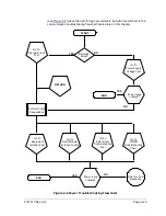
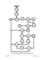
Страница 14: ...xii Figure 6 3 AC Charger Power Supply Wiring 6 28 Figure 6 4 Communication Troubleshooting Flowchart 6 30 ...
Страница 27: ...Page 2 8 2101510 Rev AG Figure 2 4 NGC8206 Enclosure Figure 2 5 NGC8206 Enclosure Left Side ...
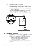
Страница 60: ...2101510 Rev AG Page 2 41 hex socket set screw on cap Figure 2 32 Explosion Proof AC Power Supply ...


