11
4
ELECTRICAL INSTALLATION…
4.4.3
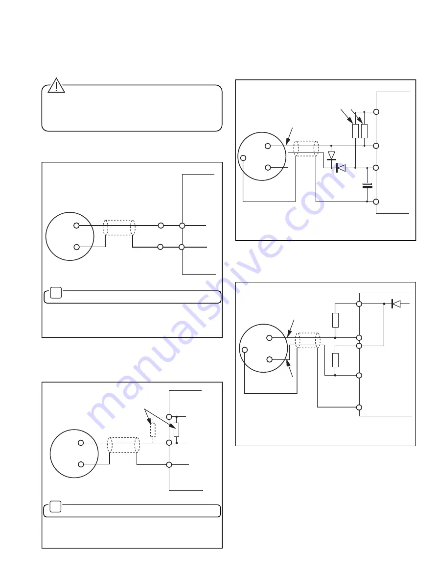
Bi-directional Data Logger – Fig. 4.4
Where an AquaProbe is replacing an existing electro-
mechanical probe the following circuitry may be required.
4.4
Data Logger Connections – Figs. 4.2 to 4.5
If required, the transmitter may be connected to a data logger
using suitable cables – see Section 8.1. Additional connection
details are shown in Table 4.1 (previous page).
Caution. When connecting to remote receiving
equipment take care to ensure that large earth currents
are prevented as a result of the common zero volt
connections. Failure to observe this precaution may result
in inaccurate or unreliable operation.
4.4.1
Celia Isolated Logger – Fig. 4.2
Orange
Screen
Supplied Cable
'Celia'
Data
Logger
Brown
Blue
Ground
AquaProbe
Transmitter
19-way Plug
D
G
✶
For reverse flow and/or x10 resolution see Table 4.1
Fig. 4.2 – Connection to 'Celia' Isolated Data Logger
(x1 Forward Flow Connected)
AquaProbe
Transmitter
19-way Plug
Ground
D
G
F
X1F
(Orange)
X1R
(Blue)
100K
A
B
1N4148
1N4148
4
µ
7
16V
+ 12V
(Typ.)
Forward
Reverse
C
Common
D
Logger
Fig. 4.4 Connection to Bi-directional Data Logger
4.4.4
Cervelec WS2 Telemetry System – Fig. 4.5
AquaProbe
Transmitter
19-way Plug
Ground
D
G
F
X1F
(Orange)
X1R
(Blue)
680R
680R
Input
12
13
14
2
15
Input
24V
(isolated)
WS2
Telemetry
System
Fig. 4.5 Connection to WS2 Telemetry System
Fig. 4.3 Connection to Contact Closure Configured
Logger (x1 Forward Flow Signal Connected)
4.4.2
Data Logger Configured for Contact Closure
– Fig. 4.3
✶
For reverse flow and/or x10 resolution see Table 4.1
AquaProbe
Transmitter
19-way Plug
Pull-up Resistor,
Internal or External
if not fitted in logger
Logger
Input
Common
or 0V
Orange
Screen
D
G
Ground
Содержание Kent-Taylor AquaProbe
Страница 22: ...20 NOTES ...


