4 Repair
4.6.3. Replacement of motor, axis 4
231
3HAC028197-001 Revision: A
©
Co
py
rig
h
t 200
7-
200
8 ABB. All righ
ts reser
v
ed.
4.6.3. Replacement of motor, axis 4
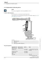
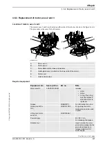
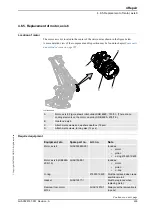
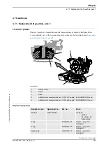
Location of motor
The motor axis 4 is located on the left hand side of the upper arm as shown in the figure below.
xx0700000061
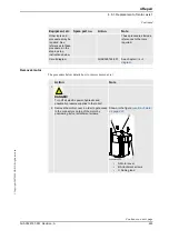
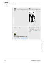
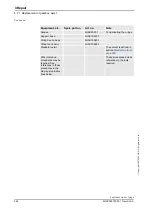
Required equipment
A
Motor, axis 4
B
Attachment screws M8X25 quality 8.8 (4 pcs)
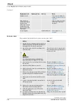
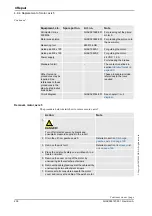
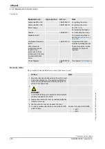
Equipment, etc.
Spare part no.
Art. no.
Note
Motor including
pinion
3HAC15889-2
Includes
•
motor
•
pinion
•
o-ring 21522012-430
O-ring
21522012-430
Must be replaced when reas-
sembling motor!
Lifting tool, motor ax
1, 4, 5
3HAC14459-1
Grease
3HAC3537-1
Used to lubricate the o-ring.
Removal tool. motor
M10x
3HAC14972-1
Always use the removal tools
in pairs!
Guide pins M8 x 100
3HAC15520-1
For guiding the motor.
Guide pins M8 x 150
3HAC15520-2
For guiding the motor.
Rotation tool
3HAC17105-1
Used to rotate the motor
pinion when mating it to the
gear, when brakes are
released with 24 VDC power
supply.
Power supply
-
24 VDC, max. 1,5 A
For releasing the brakes.
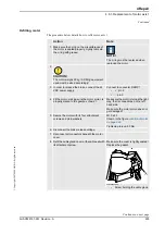
Standard toolkit
-
The content is defined in
section
.
Calibration
Pendulum toolkit
3HAC15716-1
Complete kit that also
includes operating manual.
Continues on next page
Содержание IRB 6660 - 130/3.1
Страница 1: ...Product manual Articulated robot IRB 6660 130 3 1 IRB 6660 205 1 9 M2004 ...
Страница 2: ......
Страница 14: ...How to read the product manual 3HAC028197 001 Revision A 12 Copyright 2007 2008 ABB All rights reserved ...
Страница 310: ...9 Circuit diagram 9 1 Introduction 3HAC028197 001 Revision A 308 Copyright 2007 2008 ABB All rights reserved ...
Страница 332: ... 0 1 23 3 4 5 5 6 2 70 2 888 2 9 6 0 9 9 2 A 8B C D 9 8 B ...
Страница 333: ... 2 3 4 5 5 6 2 70 2 888 2 9 6 0 9 9 1 EF 2 888 2 9 6 9 9 8 B ...
Страница 336: ... 98 2 888 7 066 0 10I 4 5 5 06 6 2 70 2 888 2 9 6 0 9 9 G E 7 F E 7 F 9 8 B ...
Страница 347: ......

