


5.2 Synchronization marks and axis movement directions
5.2.1 Synchronization marks and synchronization position for axes
Introduction
This section shows the position of the synchronization marks and the
synchronization position for each axis.
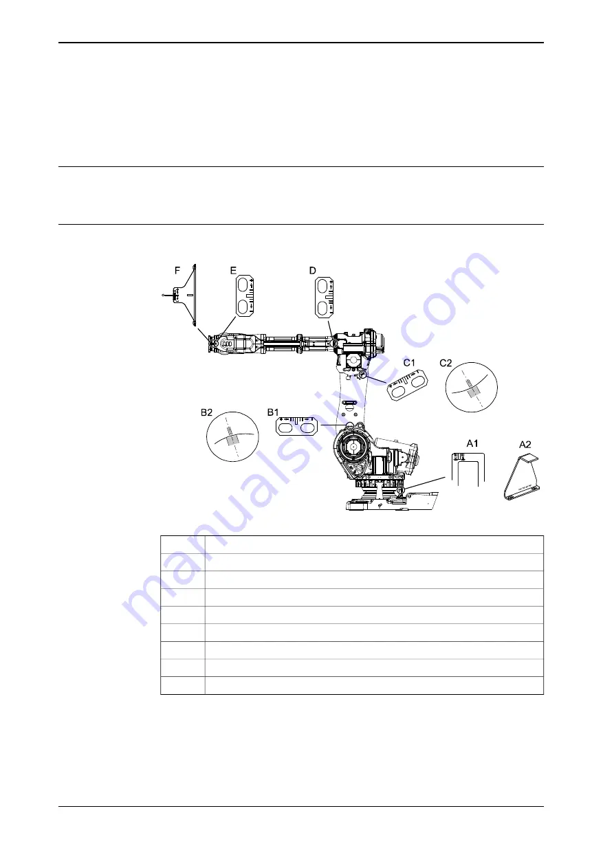
Synchronization marks, IRB 6650S
The figure shows IRB 6600, but the scales and their positions are the same.
xx0200000176
Synchronization mark, axis 1 (early design)
A1
Synchronization mark, axis 1 (later design)
A2
Synchronization mark, axis 2 (early design)
B1
Synchronization mark, axis 2 (later design)
B2
Synchronization mark, axis 3 (early design)
C1
Synchronization mark, axis 3 (later design)
C2
Synchronization mark, axis 4
D
Synchronization mark, axis 5
E
Synchronization mark, axis 6
F
Synchronization marks at axes 2 and 3
The synchronization marks at axes 2, 3 and 6, shown in the figure above, consist
of two single marks that should be positioned opposite to one another when the
robot is standing in its synchronization position. One of the marks is more narrow
than the other and should be positioned within the limits of the wider mark.
394
Product manual - IRB 6650S
3HAC020993-001 Revision: Z
© Copyright 2004-2018 ABB. All rights reserved.
5 Calibration
5.2.1 Synchronization marks and synchronization position for axes
Содержание IRB 6650S Series
Страница 1: ...ROBOTICS Product manual IRB 6650S ...
Страница 2: ...Trace back information Workspace R18 2 version a18 Checked in 2018 11 20 Skribenta version 5 3 012 ...
Страница 20: ...This page is intentionally left blank ...
Страница 50: ...This page is intentionally left blank ...
Страница 210: ...This page is intentionally left blank ...
Страница 416: ...This page is intentionally left blank ...
Страница 422: ...This page is intentionally left blank ...
Страница 426: ...This page is intentionally left blank ...
Страница 449: ......


