


Installation and Commissioning
Connecting Signals
Product Manual IRB 6400R
41
3.6
Customer connections on manipulator
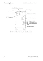
The hose for compressed air is integrated into the manipulator. There is an inlet at the
base and an outlet on the upper arm housing or on the movable part of the upper arm.
Connection: G 1/2” on the upper arm and G 1/2” at the base.
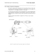
For connection of extra equipment on the manipulator, there are cables running parallel
to the manipulator’s cable harness with one Burndy 12-pin UTD 71412 SHT and one
Burndy 4-pin UTD 7104 SHT connector on the movable part of the upper arm and arm
housing.
Number of signals with CANBUS: 10 signals (50 V, 250 mA), 2 power signals
(250 V, 8 A).
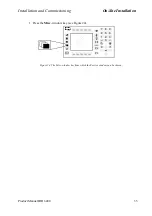
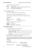
Figure 31 Location of customer connections on upper arm / arm housing.
With CANBUS
R2.CAIR
R3.CANBUS
R3.CANBUS
R2.CAIR
R2.CS
R2.CS
R2.CP
R2.CP
Содержание IRB 6400R
Страница 4: ...Description 20 Product Specification IRB 1400 M97A BaseWare OS 3 0 ...
Страница 6: ...Introduction 2 Product Manual ...
Страница 10: ...Introduction 6 Product Manual ...
Страница 12: ...Product Specification IRB 6400R 2 Product Specification IRB 6400R M99 BaseWare OS 3 2 ...
Страница 78: ...Accessories 68 Product Specification IRB 6400R M99 BaseWare OS 3 2 ...
Страница 80: ...Product Specification RobotWare 2 Product Specification RobotWare for BaseWare OS 3 2 ...
Страница 82: ...Introduction 4 Product Specification RobotWare for BaseWare OS 3 2 ...
Страница 104: ...Interbus S 3 2 26 Product Specification RobotWare for BaseWare OS 3 2 ...
Страница 110: ...I O Plus 3 2 32 Product Specification RobotWare for BaseWare OS 3 2 ...
Страница 128: ...PalletWare 50 Product Specification RobotWare for BaseWare OS 3 2 ...
Страница 132: ...Safety 2 Product Manual ...
Страница 148: ...System Description CONTENTS Page 2 Product Manual ...
Страница 158: ...Structure System Description 12 Product Manual ...
Страница 160: ...Computer System System Description 14 Product Manual ...
Страница 164: ...I O System System Description 18 Product Manual ...
Страница 168: ...Safety System System Description 22 Product Manual ...
Страница 170: ...External Axes System Description 24 Product Manual ...
Страница 174: ...Installation and Commissioning CONTENTS Page 4 Product Manual IRB 6400R ...
Страница 193: ...Installation and Commissioning On Site Installation Product Manual IRB 6400R 23 Figure 17 Cutting the cam Remove 90 30 ...
Страница 196: ...On Site Installation Installation and Commissioning 26 Product Manual IRB 6400R ...
Страница 270: ...Installing the Control Program Installation and Commissioning 100 Product Manual IRB 6400R ...
Страница 292: ...Maintenance CONTENTS Page 2 Product Manual IRB 6400R ...
Страница 299: ...Maintenance Product Manual IRB 6400R 9 Figure 4 Lubricating gearbox axis 1 4 3 1 2 ...
Страница 312: ...Troubleshooting Tools CONTENTS Page 2 Product Manual ...
Страница 350: ...Troubleshooting Tools 40 Product Manual ...
Страница 352: ...Fault tracing guide 2 Product Manual ...
Страница 362: ...Fault tracing guide 12 Product Manual ...
Страница 375: ...Motor units Repairs 12 Product Manual IRB 6400R ...
Страница 401: ...Arm System Repairs 38 Product Manual IRB 6400R ...
Страница 409: ...Cabling Repairs 46 Product Manual IRB 6400R ...
Страница 441: ...Special Tools List Repairs 80 Product Manual IRB 6400R ...
Страница 479: ...Part List and Spare Parts Product Manual IRB 6400R 38 ...
Страница 480: ...Part List and Spare Parts Product Manual IRB 6400R 39 ...
Страница 481: ...Part List and Spare Parts Product Manual IRB 6400R 40 ...


