


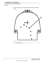

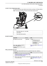
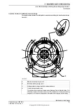
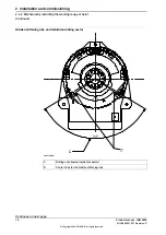
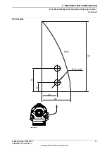
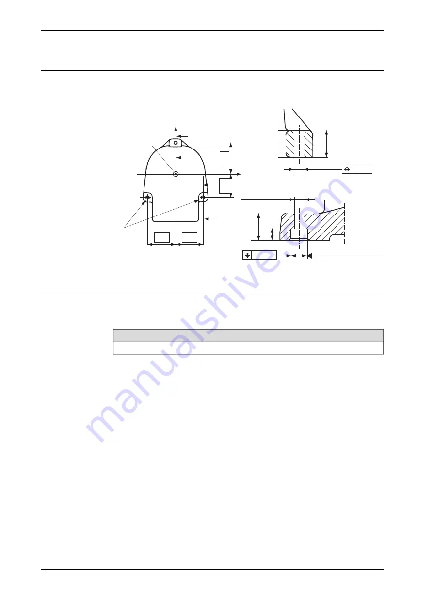
Hole configuration
The figure below shows the hole configuration of the robot base, and cross section
of the guide sleeve holes used when securing the robot.
210
280
B
A
A
260
260
(A)
Z
B
(B)
(C)
X
Y
48
Ø 0.5
D = 18.5
B - B
D = 18.5 (2x)
48
20
Ø 0.25
D = 35 H8 (2x)
+0.039
-0
A - A
xx1400002065
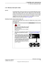
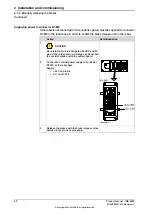
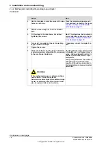
Guide sleeves
Two guide sleeves can be fitted to the two rear bolt holes to allow the same robot
to be remounted without re-adjusting the program.
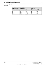
Art. no.
Equipment
2151 0024-169
Guide sleeves
62
Product manual - IRB 2400
3HAC022031-001 Revision: P
© Copyright 2004-2018 ABB. All rights reserved.
2 Installation and commissioning
2.3.3 Orienting and securing the robot
Continued
Содержание IRB 2400 Series
Страница 1: ...ROBOTICS Product manual IRB 2400 ...
Страница 2: ...Trace back information Workspace R18 1 version a9 Checked in 2018 03 22 Skribenta version 5 2 025 ...
Страница 8: ...This page is intentionally left blank ...
Страница 18: ...This page is intentionally left blank ...
Страница 204: ...This page is intentionally left blank ...
Страница 220: ...This page is intentionally left blank ...
Страница 232: ...This page is intentionally left blank ...
Страница 234: ...This page is intentionally left blank ...
Страница 240: ......
Страница 241: ......


