background image

TR A N S FOR M E R BUS H I NG S T YPE G S B 

T EC H N I C A L  G U I D E

17

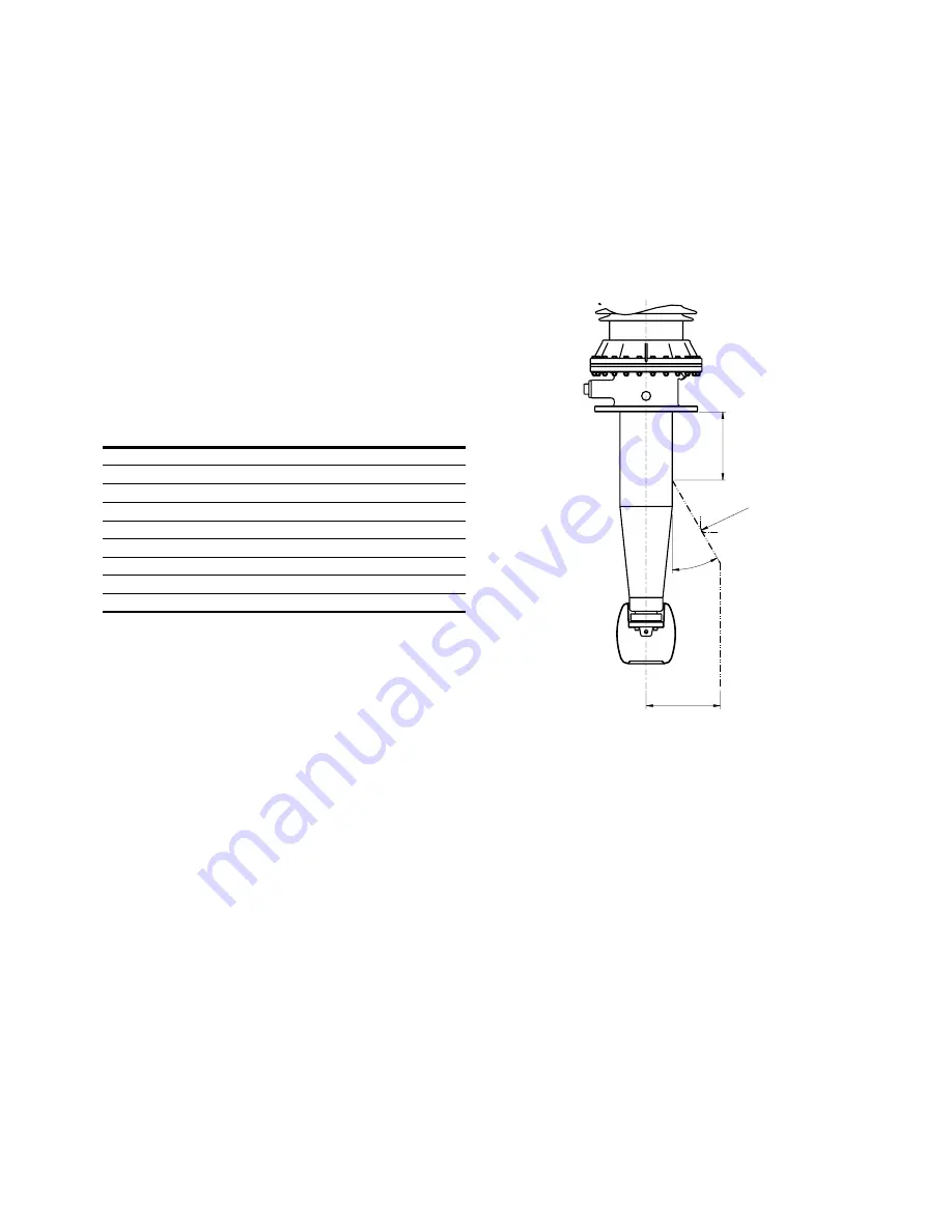
Recommendations for positioning


12 Recommendations for positioning.

30°

R

CT

min R5

The maximum stresses in the oil at the surface of the 
conductor insulation must be limited to the normal values 
for insulated conductors and similar components in the 
same transformer. The adjacent recommendations are 
intended as guidelines when complete calculations are not 
carried out.

Table 11. Recommendations for positioning.

Type GSB

CT (mm)

R (mm)

245

300

325

600

325

362

300

360

600

360

420

300

460

600

460

550

300

510

600

510

Содержание GSB 245

Страница 1: ... 1ZSC000563 A AC EN REV 9 Transformer bushings type GSB Technical guide ...

Страница 2: ...odify the contents of this document without prior notice With regard to purchase orders the agreed particulars shall prevail ABB does not accept any responsibility whatsoever for potential errors or possible lack of information in this document We reserve all rights in this document and in the subject matter and illustrations contained therein Any reproduction disclosure to third parties or utiliz...

Страница 3: ... Dimensions 9 Connection details 12 Outer terminal 12 Separate terminal plate with bolts 12 Outer shield 12 Inner terminal 13 Draw rod system 14 Fixed bottom contact 15 Standard end shield 15 Conductor insulation 15 Conductor loading and mechanical loading 16 Conductor loading 16 Mechanical loading 16 Recommendations for positioning 17 Ordering particulars 18 ...

Страница 4: ......

Страница 5: ...ding 90 from the vertical The standard colour of the composite insulator is ANSI 70 light gray Standards The GSB bushing is designed and tested according to IEC 60137 and IEEE C57 19 00 01 Features and benefits Solid Oil free Reduced risk of fire Oil leakage from the bushing eliminated Seals the transformer Reduced risk of fire Risk of oil leakage from the transformer reduced Non shattering materi...

Страница 6: ...ollution level According to specific creepage distance and IEC 60815 Immersion medium Transformer oil Oil temperatures for normal load Maximum daily mean temperature 90 C Maximum temporary temperature 100 C Oil temperatures for long and short time overload Maximum daily mean temperature 90 C Maximum temporary temperature 115 C Max pressure of medium 100 kPa over pressure Angle of mounting Horizont...

Страница 7: ...ismic qualification GSB bushing with composite insulator have been qualified in shake table tests for High Performance Level IEEE 693 2005 Executed tests also satifies seismic requirements for AG5 0 5g of IEC TS 61463 Test tap The outer conducting layer of the condenser body is connected to the insulated test tap During operation the protective cap must be fitted to ground the outer conducting lay...

Страница 8: ...0 1600 Cu conductor 3150 3150 2500 2500 2500 Rated frequency Hz 50 60 50 60 50 60 50 60 50 60 Temporary over voltage kV IEC phase to ground voltage 196 290 336 440 440 Wet power frequency AC kV 460 n a 650 750 750 Dry power frequency routine test 1 min kV 506 561 695 750 750 Nominal capacitance between conductor and test tap C1 10 pF with space for current transformer CT 300 600 mm 663 769 619 701...

Страница 9: ...ECHNIC AL GUIDE 9 Dimensions 05 Dimensions R2 2x R5 2x 55 23 7 48 65 R8 2x 8 15 A Porcelain B Composite D5 D6 Ø 23 12x M12 D7 L4 D4 D1 L L1 B A D2 L3 CT L2 Ø 70 Center hole diameter Ø 96 D3 39 70 51 66 18 2x 10 2x R8 2x R10 2x R4 5 2x ...

Страница 10: ...6 kV 420 901420 AAA Porcelain brown 901420 BAA Porcelain grey Test tap 3920 3235 1090 345 195 901420 ABA Porcelain brown 901420 BBA Porcelain grey Voltage tap 6 kV 901420 AAB Porcelain brown 901420 BAB Porcelain grey Test tap 1390 901420 ABB Porcelain brown 901420 BBB Porcelain grey Voltage tap 6 kV 901420 CAA CCA Composite Test tap 1090 CBA CDA Composite Voltage tap 6 kV CAB CCB Composite Test ta...

Страница 11: ...20 400 406 492 274 335 535 400 450 1600 3150 300 720 820 10371 9955 600 750 850 372 446 300 450 550 12861 12345 600 480 580 412 527 300 335 560 450 500 1600 2500 300 940 1050 11852 11550 600 970 1080 376 480 300 540 650 14322 13747 600 570 680 466 602 374 455 635 500 550 1600 2500 300 1550 1690 15519 15125 600 1610 1750 448 548 300 950 1090 19242 18755 600 1010 1150 466 602 374 455 635 500 550 160...

Страница 12: ...tact The contact surface is located inside the gasket and is thus well protected from corrosion Finally the tightening ring with the gasket is pressed against the stud by means of 6 additional bolts M8 The outer terminal is available in a number of standard configurations Other configurations can be supplied on request Table 5 Outer terminal Max torque on outer terminal 200 Nm Cat No Material Plat...

Страница 13: ...rminal with a hole for brazing the cable and a divided ring for mounting To fit the end shield an adapter Cat No 1ZSC999002 AAG is used If an inner terminal is used no current passes through the center tube Table 6 Inner terminal Cat No Conductor diameter D3 mm 1ZSC999005 AAA 15 1ZSC999005 AAB 30 1ZSC999005 AAC 40 1ZSC999005 AAD 42 08 Inner terminal 72 D3 ...

Страница 14: ...f different materials designed to give the required contact load at all temperatures The draw rod is divided into two parts at level with the flange The lower draw rod includes bottom contact guide cone rod and joint The upper draw rod consists of compensating device rods joints washer and nut 09 Draw rod system If required to meet the transport conditions an additional joint can be positioned at ...

Страница 15: ...e outer terminal End shield Cat No 1ZSC999003 AEA is suitable for the bottom contact Type 2 bottom contact cannot be used with fixed bottom contact Standard end shield The end shield is made of aluminium and coated with insulating epoxy paint or 3 mm of pressboard The design enables easy installation and should be used with standard draw rod bottom contact the fixed bottom contact system and the a...

Страница 16: ...rrents and temperatures Short time current The rated thermal short time current Ith is calculated according to IEC 60137 Table 9 Short time current Type GSB Rated current A Short time current Ith kA rms 2 s Dynamic current Id kA peak 245 2000 100 250 3150 100 250 362 1600 100 250 3150 100 250 420 1600 100 250 2500 100 250 550 1600 100 250 2500 100 250 Mechanical loading The cantilever operational ...

Страница 17: ... of the conductor insulation must be limited to the normal values for insulated conductors and similar components in the same transformer The adjacent recommendations are intended as guidelines when complete calculations are not carried out Table 11 Recommendations for positioning Type GSB CT mm R mm 245 300 325 600 325 362 300 360 600 360 420 300 460 600 460 550 300 510 600 510 ...

Страница 18: ...rmal routine tests Ordering example 1 Bushing GSB 245 2000 0 6 Composite test tap 1ZSC901245 CAB Connection Draw rod lower additional joint H1 300 mm 1ZSC999006 Draw rod upper bottom contact type 1 standard 1ZSC999007 Outer terminal Copper Silver D2 30 mm 1ZSC999001 AAC End shield Epoxy insulated 1ZSC999003 AEA Ordering example 2 Bushing GSB 420 1600 0 3 Composite voltage tap 1ZSC901420 CBA Connec...

Страница 19: ......

Страница 20: ...ponents SE 771 80 Ludvika Sweden E mail sales se abb com www abb com transformercomponents 1ZSC000563 AAC en Rev 9 2018 11 15 Copyright 2018 ABB All rights reserved Specifications subject to change without notice ...

Отзывы: