


ABB
LGR-ICOS
™ GLA232 Series Methane/Ethane Analyzer User Manual
ABB PROPRIETARY INFORMATION
18
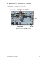
Figure 5: Analyzer Plumbing Diagram
The gas enters the
⅜
inch Swagelok sample inlet, passes through a 40 SLM flow meter, and is
filtered by a 2
μ
m screen filter. An upstream pressure controller regulates the pressure as
measured in the cell to a specific set point (typically 300 Torr). The gas travels through the
optical cell (protected by a check valve) and out through the internal pump exhaust port. By
default, the pump exhausts directly into the analyzer, but can optionally be connected to the
waste port on the analyzer rear panel.
Gas Inlet/Outlet Connections
The gas inlet and optional outlet ports are located on the rear panel of the analyzer. See Figure 6
for the gas inlet. See Figure 3 for the gas outlet port (
EXHAUST WASTE
).
NOTE
Figure 6 displays a water dropout trap and additional 2 µm filter used in
MobileGuard™ systems.
Gas to be measured is connected to the
⅜
inch Swagelok inlet port.
The ½ inch Swagelok
EXHAUST WASTE
port may optionally be connected to the internal pump
and routed to a ventilation system.
During normal operation, the pump draws the sample through the analyzer inlet and exhausts
the sample directly into the analyzer.