


Endura AZ series integral and remote transmitter
Combustion oxygen monitor
4 Electrical Installation
IM/AZ20E–EN Rev. F
21
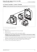
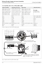
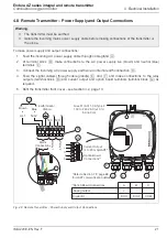
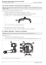
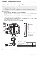
4.8 Remote Transmitter – Power Supply and Output Connections
To make power supply and output connections:
1.
Feed the incoming AC power supply cable through cable gland
A
.
2.
At terminal block
B
, make connections to the AC power supply live (brown) and neutral (blue)
terminals
C
.
3.
Connect the incoming AC power supply earth wire to internal earth connection
D
.
4.
Feed the signal cable(s) through cable gland(s)
E
and
F
and make connections to the relay
outputs (terminal block
B
) and current output and option board terminals (terminal block
G
) as
required.
5.
Refit the transmitter front cover – see Section 4.2, page 13.
Warning.
The transmitter must be earthed.
Isolate the incoming mains power supply cable before making connections at the transmitter or
the probe.
Fig. 4.9 Remote Transmitter – Power Supply and Output Connections
+
C
B
A
C
C
N/C N/C
N/L2
L/L1
A
E
D
C
D
B
G
F
Fuse F1 (AC) 1.0 A Type F
100 to 240 V AC (±10 %)
50 / 60 Hz
Blue
Earth (Green /
Yellow)
Brown
Re
la
y 2
Re
la
y 1
Current Output
(4 to 20 mA) HART
*
Option Board
Connections**
Mains
Connections
*Refer to Section 7.2, page 69
for HART communication details
**Option Board Connections
Analog output
Digital I/O
A
+
DIO1
B
–
DIO2
C
COM


