


ABB | SACE Emax 2
34 | © 2017
ABB |
1SDH000999R0002 - ECN000058721 - Rev. B
Ekip Dip protection trip unit | 1 - Operator interface
Ekip Dip protection trip unit
1 - Operator interface
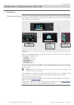
Introduction
The operator interface of the Ekip Dip protection trip unit allows you to:
• Set the parameters relating to the available protections.
• View the status of the trip unit and alarms.
• Connect to the frontal connector to communicate and perform the opening test.
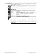
Components of the interface
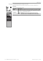
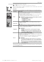
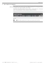
The Ekip Dip operator interface appears as follows:
Figure 67
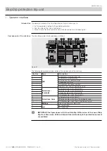
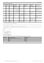
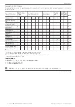
The following table provides a description of the components of the interface:
Position
Type
Description
A
LED
L Protection LED (alarm and trip)
B
L Protection LED (pre-alarm)
C
S Protection LED (alarm and trip)
D
I Protection LED (trip)
E
G Protection LED (alarm and trip)
F
Power-on LED (trip unit powered and on)
G
Protections:
thresholds
L Protection dip-switch (threshold I1)
H
S Protection dip-switch (threshold I2)
I
I Protection dip-switch (threshold I3)
L
G Protection dip-switch (threshold I4)
M
Protections: times
L Protection dip-switch (time t1)
N
S Protection dip-switch (time t2 and type of curve)
Or
G Protection dip-switch (time t4 and type of curve)
P
Settings
Neutral and frequency dip-switch
Q
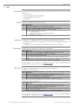
Test
Test pushbutton
R
Test connector
IMPORTANT: the figure above refers to an Ekip Dip, LSIG version. In the case of Ekip
Dip LI or LSI versions, LEDs and dip-switches related only to the protections present
are available.


