Electrical installation
60
3ADW000462R0301 DCS880 Hardware Manual e c
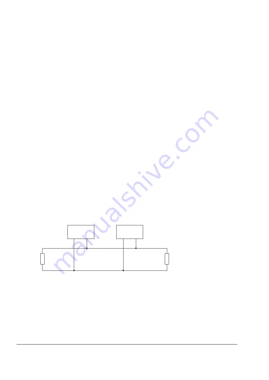
DCSLink wiring
The DCSLink is a 500 kBaud serial communication between drives and drives to field exciters.
It is based on CAN hardware and using twisted cables.
The topology is a bus system.
Switched OFF nodes can remain in the bus and do not disturb the serial communication.
The function of the interface is predefined:
1. Mailbox function for drive to drive communication (e.g. master - follower).
2. Communication to field exciter types DCF803, DCF804 and large field exciters using standard
DCS880 modules.
3. Communication for 12-pulse operation, DCS880 to DCS880.
Cabling
Every bus device requires its own individual node number.
Only two physical ends are allowed for the bus system.
The bus termination of the twisted pair cable is done using a termination resistor of 120 Ohm inside
the drives or field exciters.
The termination resistance of 120 Ohm is selected for typical twisted pair cables. The cables must be
terminated at both ends. This is done using jumpers or switches.
Preferred cable type: DEVICENET
Supplier:
Helu Kabel, Germany; type 81910PUR
Belden, USA; type 3084A
SF_DCS_002_can-bus_a.ai
Node 1
CAN_H
...
CAN_L
Node n
120 Ohm
1 %, 1/4 W
120 Ohm
1 %, 1/4 W


