


ControlMaster CM30, CM50 and CMF310
Universal process controllers,
1
/
4
,
1
/
2
DIN and fieldmount
6 Basic Level
IM/CM/ED–EN Rev. X
31
…Basic
Loop 1 (2) Mot Valve
Motorized Valve Output With Feedback
Motorized Valve Output Without Feedback (Boundless)
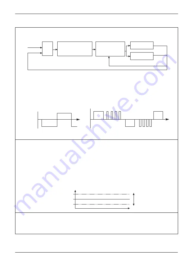
A motorized valve output without feedback (boundless) process controller provides an output that is effectively the
time derivative of the required regulator position (the controller signals the regulator, not where to go to [position
derivative], but in the direction to travel and how far to move) by a series of integral action pulses. Therefore, the
controller does not need to know the absolute regulator position and is not affected when the regulator reaches the
upper or lower limit, as determined by the regulator's limit switches (hence the term ‘boundless').
When a deviation from setpoint is introduced, the regulator is driven for a length of time equivalent to the proportional
step. The regulator is then driven by integral action pulses until the deviation is within the deadband setting.
Ratio
Bias
The required valve position = (Ratio x PID O/P) + Bias.
Note
. Ratio and Bias are applicable only to motorized valve with feedback – see above.
Deadband
With Feedback
The deadband is expressed as a % of the valve position. For example, if the valve is set to
be driven to the 50 % open position and the deadband is set to 4 %, the motor stops
driving at 48 %. The deadband is between 48 % and 52 %.
Without Feedback
(Boundless)
The deadband is expressed in engineering units. For example, if the (Boundless)
engineering range is 0 to 150 litres and the set point is 75 litres, when the deaband is set to
10 litres, the deadband is between 70 and 80 litres.
Travel Time
For motorized valve without feedback (see above), this parameter is used to control the
valve movement.
For motorized valve with feedback, the time entered is compared with the actual valve
movement. If the valve is sticking, a diagnostic message is generated (set
Travel Time
to 0 s
to disable this feature).
PV
SPT
(OP x Ratio) + Bias
PID
Motorized
Valve
Controller
Open Relay
Close Relay
Position Feedback
+
Control
Deviation
Proportional
Step
Raise
Lower
Integral Action Pulses
Proportional
Step
Integral Action
Pulses
Time
Time
PV / Valve Position
Deadband
(centred around
required position)
Set Point


