


Single and Dual Input Analyzers for pH/Redox (ORP)
AX416, AX436, AX460, AX466 & AX468
6 INSTALLATION
IM/AX4PH
Issue 9
51
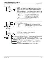
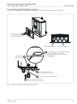
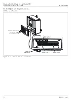
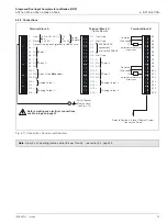
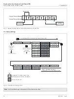
6.4.2 Connections
Fig. 6.9 Connections, Wall-/Pipe-mount Analyzer
Note.
Relay 3 can be configured to control the wash facility - see section 5.4, page 33.
Temperature Compensator
Connections
B16
B15
B14
B13
B12
B11
B10
B9
B8
B7
B6
B5
B4
B3
B2
B1
TC
Thir
d Lead
Common
TC
Thir
d Lead
Common
Temperature Compensator
Connections
PROFIBUS DP
connections –
refer to IM/PROBUS
Before making any electrical connections,
see Warnings on page 47
C1
Not used
C2
Not used
C3
C4
C5
C6
Not used
C7
C
C8
NC
Relay 4
C9
NO
C10
C
C11
NC
Relay 5
C12
NO
C13
+
Analog Output 3
C14
—
C15
+
Analog Output 4
C16
—
Earth (Ground)
Stud on Case
(see Fig. 6.8)
Line
L
Neutral
N
E
CA
4
Relay 1
NC
A5
NO
A6
CA
7
Relay 2
NC
A8
NO
A9
C
A10
Relay 3 (see
Note
below)
NC
A11
NO
A12
Analog Output 1
+
A13
—
A14
Analog Output 2
+
A15
—
A16
Terminal Block A
Terminal Block B
Terminal Block C
(Option Board)
+
85 to 265 V AC
Power Supplies
12 to 24V DC
or
–
24 V AC
Refer to Section 6.6 for pH Sensor System
Connection Details
Connect supply earth (gr
ound) to stud on case


