

Parameters and firmware blocks
53
Parameters and firmware blocks
What this chapter contains
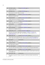
This chapter lists and describes the parameters provided by the firmware.
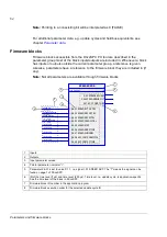
Types of parameters
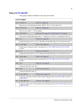
Parameters are user-adjustable operation instructions of the drive (groups 10…99).
There are four basic types of parameters: Actual signals, value parameters, value
pointer parameters and bit pointer parameters.
Actual signal
Type of parameter that is the result of a measurement or calculation by the drive.
Actual signals can be monitored, but not adjusted, by the user. Actual signals are
typically contained within parameter groups 1…9.
For additional actual signal data, e.g. update cycles and fieldbus equivalents, see
chapter
.
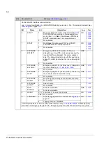
Value parameter
A value parameter has a fixed set of choices or a setting range.
Example 1: Motor phase loss supervision is activated by selecting
from
the selection list of parameter
.
Example 2: The motor nominal power (kW) is set by writing the appropriate value to
parameter
, e.g. 10.
Value pointer parameter
A value pointer parameter points to the value of another parameter. The source
parameter is given in format
P.xx.yy
, where xx = Parameter group; yy = Parameter
index. In addition, value pointer parameters often have a set of pre-selected choices.
Example: Motor current signal,
, is connected to analogue
output AO1 by setting parameter
to value P.01.05.
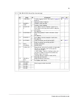
Bit pointer parameter
A bit pointer parameter points to the value of a bit in another parameter, or can be
fixed to 0 (FALSE) or 1 (TRUE). In addition, bit pointer parameters often have a set
of pre-selected choices.
When adjusting a bit pointer parameter on the optional control panel, CONST is
selected in order to fix the value to 0 (displayed as “C.FALSE”) or 1 (“C.TRUE”).
POINTER is selected to define a source from another parameter.
A pointer value is given in format
P.xx.yy.zz
, where xx = Parameter group,
yy = Parameter index, zz = Bit number.
Example: Digital input DI5 status,
bit 4, is used for brake
supervision by setting parameter
to value P.02.01.04.
Содержание ACSM1 Series
Страница 1: ...ACSM1 Firmware Manual ACSM1 Speed and Torque Control Program...
Страница 2: ......
Страница 4: ......
Страница 12: ...Table of contents 12...
Страница 49: ...Drive control and features 49...
Страница 282: ...Standard function blocks 282...
Страница 306: ...Application program template 306...
Страница 312: ...Control chain block diagrams 312...
Страница 331: ...331...
Страница 332: ...332...
Страница 333: ......


