background image

Introduction to the manual

Contents of this manual

This chapter gives basic information on the manual.

Applicability

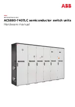
This manual is applicable with ACS880-7407LC semiconductor switch units.

Safety instructions

Obey all safety instructions delivered with the drive.

• Read the

complete safety instructions

before you install, commission, use or service

the drive. The complete safety instructions are given in

ACS880 liquid-cooled multidrive

cabinets and modules safety instructions

(3AXD50000048633 [English]).

• Read the

software-function-specific warnings and notes

before changing the default

settings of a function. For each function, the warnings and notes are given in the section
describing the related user-adjustable parameters.

• Read the

task-specific safety instructions

before starting the task. See the section

describing the task.

Target audience

This manual is intended for people who plan the installation, install, start-up and do
maintenance work on the drive, or create instructions for the end user of the drive concerning
the installation and maintenance of the drive.

Read the manual before working on the drive. You are expected to know the fundamentals
of electricity, wiring, electrical components and electrical schematic symbols.

1

Introduction to the manual 9

Содержание ACS880-7407LC

Страница 1: ... ABB INDUSTRIAL DRIVES ACS880 7407LC semiconductor switch units Hardware manual ...

Страница 2: ......

Страница 3: ...ACS880 7407LC semiconductor switch units Hardware manual Table of contents 3 Electrical installation 4 Start up 3AXD50000738984 Rev A EN Original instructions EFFECTIVE 2021 10 01 ...

Страница 4: ......

Страница 5: ... 16 Layout of a drive system with a semiconductor switch unit 17 Layout of a semiconductor switch unit 18 Control of the semiconductor switch unit 19 Type designation label s 20 Type designation key 20 Basic code 20 Option codes 3 Electrical installation 23 Contents of this chapter 24 Electrical safety precautions 26 Connecting the control cables 26 Default control connection diagram 27 Connection...

Страница 6: ...0 Cooling system parts 50 Cooling circuit overview 51 Coolant distribution manifold kits 52 Piping 52 Heat exchanger 53 Cooling fan 53 Pipe connector for the DC breaker switch 9 Internal cooling circuit 55 Contents of this chapter 55 Cooling circuit of the semiconductor switch unit 10 Technical data 57 Contents of this chapter 57 Electrical ratings 58 Fuses option F260 58 Dimensions and weights 58...

Страница 7: ...61 Applicable standards 61 Markings 62 Disclaimers 62 Generic disclaimer 62 Cybersecurity disclaimer Further information Table of contents 7 ...

Страница 8: ...8 ...

Страница 9: ...cific warnings and notes before changing the default settings of a function For each function the warnings and notes are given in the section describing the related user adjustable parameters Read the task specific safety instructions before starting the task See the section describing the task Target audience This manual is intended for people who plan the installation install start up and do mai...

Страница 10: ...d modules safety instructions 3AXD50000048634 ACS880 liquid cooled multidrive cabinets and modules electrical planning instructions 3AXD50000048635 ACS880 liquid cooled multidrive cabinets mechanical installation instructions 3AXD50000126880 CIO 01 I O module for distributed I O bus control user s manual Supply unit manuals 3AXD50000174782 ACS880 207LC IGBT supply units hardware manual 3AUA0000131...

Страница 11: ...mposer start up and maintenance PC tool user s manual 3AXD50000210268 Converter module lifting device for drive cabinets hardware manual Manuals for I O extension modules fieldbus adapters safety options etc You can find manuals on the Internet See www abb com drives documents For manuals not available in the document library contact your local ABB representative Related DC breaker switch manuals ...

Страница 12: ...12 ...

Страница 13: ...er switch can be connected either to the DC or DC busbar If it is necessary to break the fault current in both poles it is possible to add two units and DC breaker switches into the system one connected to DC busbar and the other to DC busbar Liquid cooled Bidirectional functionality Three sizes When necessary the unit can be equipped with fuses for backup protection option F260 Refer to the appro...

Страница 14: ...rts the voltage to DC The DC bus distributes DC voltage to the inverter units and other units that are optionally included in the delivery such as a semiconductor switch unit 1 3 4 5 5 6 2 A B C C D 7 8 Incoming unit A Supply unit B Inverter unit C Semiconductor switch unit D AC supply 1 Main breaker or main contactor and main switch disconnector 2 Supply module 3 DC bus 4 Inverter modules 5 Motor...

Страница 15: ...DC busbar connection default configuration option F322 On the middle DC busbar connection option F323 On the right DC busbar connection and DC busbar connection option F322 and F323 There are three unit sizes available frames SS1 SSU2 and SSU3 Fuses option F260 2 Operation principle and hardware description 15 ...

Страница 16: ...e system with a semiconductor switch unit 1 2 3 4 5 Auxiliary control cubicle 1 Incoming cubicle AC 2 Supply module cubicle 3 Supply unit 1 3 Inverter unit 4 Semiconductor switch unit 5 16 Operation principle and hardware description ...

Страница 17: ...lock for external control connections X330 3 Modbus connector Ethernet RJ485 R3 1 X20 on the breaker control interface unit behind the support 4 Backup fuses F3 1 F3 2 option F260 5 Cooling inlet manifold with stop and drain valves 6 Heat exchanger 7 Fan G115 11 8 Cooling outlet manifold with stop and drain valves 9 Operation principle and hardware description 17 ...

Страница 18: ...1 2 Green indicator P30 2 DC breaker switch closed 1 Yellow indicator P30 1 DC breaker switch open 2 See Default control connection diagram page 26 for information on the control signal interface 18 Operation principle and hardware description ...

Страница 19: ...A 1190403889 Output MADE IN FINLAND SSU2 FRAME IP42 Liquid cooling Type designation 1 Frame size 2 Cooling system and other additional data 3 Degree of protection 4 Ratings 5 Valid markings See ACS880 liquid cooled multidrive cabinets and modules electrical planning instruc tions 3AXD50000048634 English 6 Serial number The first digit of the serial number refers to the manufacturing plant The next...

Страница 20: ...Option codes The table below lists the option codes Description Code 50 Hz supply frequency A012 60 Hz supply frequency A013 IP42 UL Type 1 Filtered B054 IP54 UL Type 12 B055 Marine construction C121 Plinth height 100 mm C164 Door hinges on left C176 Plinth height 200 mm C179 Marine product certification issued by DNV GL C205 Marine product certification issued by the American Bureau of Shipping A...

Страница 21: ...ing class A2 G339 Wire marking class A3 G340 Wire marking class B1 G341 Wire marking class C1 G342 Cable gland plates 3 mm steel undrilled H358 Cable gland plates 3 mm aluminum undrilled H364 Cable gland plates 6 mm brass undrilled H365 Control cabling through floor of cabinet H367 Control cabling through roof of cabinet H368 Special color RAL Classic P913 Special color other than RAL Classic P966...

Страница 22: ...22 ...

Страница 23: ... Contents of this chapter This chapter contains the electrical safety precautions and the instructions for connecting the external control cabling to the semiconductor switch unit ACS880 7407LC 3 Electrical installation 23 11 ...

Страница 24: ...nnector if present and all other possible disconnecting devices that isolate the drive from dangerous voltage sources In the liquid cooling unit if present open the switch disconnector of the cooling pumps If you have a permanent magnet motor connected to the drive disconnect the motor from the drive with a safety switch or by other means Disconnect all dangerous external voltages from the control...

Страница 25: ...DC and UDC and the grounding PE terminal is zero In cabinet built drives measure between the drive DC busbars and and the grounding PE busbar WARNING The busbars inside the cabinet of liquid cooled drives are partially coated Measurements made through the coating are potentially unreliable so only measure at uncoated portions Note that the coating does not constitute a safe or touch proof insulati...

Страница 26: ...t between X330 6 and X330 7 DC breaker switch is disabled not in operation Closed control circuit DC breaker switch is enabled in operation 1 External trigger input signal open close command 2 Open control circuit between X330 8 and X330 9 Open command Closed control circuit Close command After the power up the control circuit must be kept open a while until the DC breaker switch is ready for oper...

Страница 27: ...27 4 Run the cables to the terminal block X330 a and connect See section Default I O connection diagram a Grounding the outer shields of the control cables at the cabinet entry Ground the outer shields of all control cables 360 degrees at the EMI conductive cushions as follows example constructions are shown below the actual hardware may vary 1 Loosen the tightening screws of the EMI conductive cu...

Страница 28: ...d exposed B Stripped part covered with copper foil C Cable shield 1 Copper foil 2 Shielded twisted pair 3 Grounding wire 4 Note for top entry of cables When each cable has its own rubber grommet sufficient IP and EMC protection can be achieved However if there is more than one cable per grommet plan the installation beforehand as follows 1 Make a list of the cables coming to the cabinet 2 Sort the...

Страница 29: ... to allow the frame to open fully Connecting to the inverter control unit A41 Connect the conductors to the appropriate terminals see page 127 of the control uni terminal block X504 option L504 Connect the inner twisted pair shields and all separate grounding wires to the groundi clamps below the control unit The drawing below represents a drive with additional I O terminal block option L504 Witho...

Страница 30: ...30 ...

Страница 31: ...ke sure that all external auxiliary circuits are switched off and disconnected See the start up instruc tions in the supply unit hardware manual Make sure that the supply unit is switched off and the drive system has been isolated from the supply network Open the main disconnecting device of the drive Crank in the main breaker Q1 option F255 or open the main switch disconnector option F253 Make su...

Страница 32: ...tage to the input terminals of the drive supply unit Close the main breaker of the supply transformer Close the main disconnecting device of the drive Crank in the main breaker Q1 option F255 or close the main switch disconnector option F253 Close the auxiliary voltage switch Q21 of the drive supply unit Tuning the settings of the DC breaker switch in the semiconductor switch unit The parameter se...

Страница 33: ...During the normal operation of the drive the DC breaker switch is closed and it monitors the system status If the DC breaker switch detects a fault situation it goes to the Fault mode and trips opens See Fault mode of the DC breaker switch page 35 Adjusting the settings of the DC breaker switch The parameter settings of the DC breaker switch are adjusted by ABB for each delivery on basis of the pr...

Страница 34: ...34 ...

Страница 35: ...ch goes into a Fault mode when the DC breaker detects that an environment sensor is out of range an overload and the External trigger input signal is still high closed circuit an overcurrent and the External trigger input signal is still high closed circuit an internal fault When the DC breaker switch goes into the Fault mode it trips opens It is not possible to close the DC breaker switch To go b...

Страница 36: ...36 ...

Страница 37: ...e maintenance tasks which can be done by the end user The complete maintenance schedule is available on the Internet www abb com drivesservices For more information consult your local ABB Service representative www abb com searchchannels Description of symbols Description Action Inspection visual inspection and maintenance action if needed I Performance of on off site work commissioning tests meas...

Страница 38: ...eaker switch R R Cooling fans 230 VAC 50 60Hz R R R Cooling fans 115 VAC 50 60Hz I I I I I I I DC Breaker switch Astrol See Astrol Maintenance Plan AD 10811 041 www astrol ch Aging R Cabinet auxiliary power supplies Note Maintenance and component replacement intervals are based on the assumption that the equipment is operated within the specified ratings and ambient conditions ABB recommends annua...

Страница 39: ...tenance work 1 Stop the drive and do the steps in section Electrical safety precautions page 24 before you start the work 2 Clean the exterior of the drive Use vacuum cleaner with an antistatic hose and nozzle soft brush dry or damp not wet cleaning cloth Moisten with clean water or mild detergent pH 5 9 for metal pH 5 7 for plastic WARNING Prevent water from entering the drive Never use excessive...

Страница 40: ...long sleeves Some parts have sharp edges 1 Repeat the steps described in section Electrical safety precautions page 24 2 Remove any shrouding in front of the cooling fan in case of marine construction C121 3 Disconnect the fan wiring 4 Undo the two retaining screws a 5 Pull the fan outwards to separate it from the heat exchanger housing 6 Install new fan in reverse order Align the guide pins b at ...

Страница 41: ... inside the cabinet Heat gun for warming up pipe ends for easier removal An empty pallet for removing the old DC breaker switch out of the site WARNING Obey the safety instructions of the drive If you ignore them injury or death or damage to the equipment can occur If you are not a qualified electrical professional do not do installation or maintenance work WARNING Beware of hot coolant Do not wor...

Страница 42: ...ty precautions page 24 2 Open the door of the cubicle 3 Remove the shrouds at the top and bottom of the cubicle option C121 4 Disconnect any cabling from the control interface of the DC breaker switch on top Mark down the connections for later use 42 Maintenance ...

Страница 43: ...eaker switch Remove the bolts a that attach the busbar assemblies b to the busbars of the DC breaker switch Pull the bolts and rear busbar plates out of the cabinet Remove the bolts c at the top of the busbar assemblies and remove the busbars assemblies completely a c b B If the semiconductor unit is equipped with fuses with option F260 Remove the lower fuse busbars WARNING Be very careful when yo...

Страница 44: ... below Pull out the lower fuse busbars a c b 6 Disconnect the cooling circuit of the DC breaker switch from the drive cooling system Drain the cooling circuit Close the inlet stop valve a and outlet stop valve b Lead the drain hoses c on both side of the cubicle into a suitable container Open the drain valves d on both side of the cubicle and drain the cooling circuit of the DC breaker switch a d ...

Страница 45: ...tension bar Pull the pipe out of the connector Remove the pipe connector b Recommendation Use a 34 mm open jaw crowfoot wrench with extension bar b a 8 Remove the upper and lower supports of the DC breaker switch Remove the screws a that attach the upper and lower supports b to the cabinet side frames Remove the bolts c that attach the upper and lower supports to the DC breaker switch and to the c...

Страница 46: ...ing eyes a when the screw holes for the front lifting eyes are on the front side of the brackets b of the cabinet frame Attach the front lifting slings to the front lifting eyes b a b a 10 Install the rear lifting eyes and attach the hoist Pull the DC breaker switch outwards a little more until the screw holes for the rear lifting eyes are on the front side of the brackets of the cabinet frame Ins...

Страница 47: ...t the DC breaker switch on a pallet 13 Protect the connectors and interface unit on top of the DC breaker switch Attach the DC breaker switch onto the pallet to prevent it from falling 14 Install a new DC breaker switch in reverse order Tighten the busbars to 70 N m and pipe connector to 60 N m Install a new gasket for the pipe connector Recommended gasket type See Tools page 41 Maintenance 47 ...

Страница 48: ...in section Electrical safety precautions page 24 2 Open the door of the cubicle 3 Remove the shroud s in front of the fuses option C121 4 Loosen the screws on top and on bottom of the fuses and carefully remove the screws and the washers from the cabinet Make note of the correct order of the washers on the screws 5 Pull the fuse blocks out 6 Insert new fuse blocks and install the screws and washer...

Страница 49: ...builders who construct the unit out of components and need to acquire them separately The information is not relevant for the cabinets installed semiconductor switch units ACS880 7407LC The cabinet installed units include all components as standard DC breaker switch Refer to Technical data page 57 for the DC breaker switch types DC breaker switches are available from Astrol www astrol ch 8 Orderin...

Страница 50: ...DC breaker switch ABB kit available 3 Coolant distribution manifold kits page 51 Inlet or outlet manifolds 4 Coolant distribution manifold kits page 51 Inlet or outlet stop valves part of the manifold kits Pipe connectors See no 7 5 Coolant distribution manifold kits page 51 Inlet or outlet drain valves part of the manifold kits 6 Coolant distribution manifold kits page 51 Drain pipe connector The...

Страница 51: ...alves to manifolds Connectors for PA piping Plugs for unused piping connectors Chokes for flow limitation not used with the ACS880 7407LC You must order the following parts separately as they are not included in the manifold kits Connectors to attach to inlet outlet and drain valves Connectors to attach to main pipes Pipes between main pipe and inlet outlet valves Main pipes Drain pipes Note The i...

Страница 52: ...40 8 6 mm L50m PA pipe Note The piping between the manifolds and main pipes 1 the drain pipes 2 or the main pipes 3 are not part of the standard offering Contact ABB for availability 1 2 2 3 3 Heat exchanger The kits inlcude the heat exchanger and the connectors for piping Illustration Kit code Ordering code Qty Used with L 468 8 440 3AXD50000041265 1 per module All enclosure types 52 Ordering inf...

Страница 53: ...The fan is selected according to the auxiliary voltage Illustration Ordering code Qty Auxiliary voltage 3AXD50000043886 1 module 230 V AC 50 60 Hz 3AXD50000045414 1 module 115 V AC 50 60 Hz Pipe connector for the DC breaker switch Illustration Ordering code Qty Components 1 2 3AXD50000834396 2 pcs kit Connector with gasket 1 2 pcs kit Nut for attaching pipe to connector 2 Ordering information 53 ...

Страница 54: ...54 ...

Страница 55: ... information on the internal cooling circuit of the drive refer to ACS880 107LC inverter units hardware manual 3AXD50000196111 English Cooling circuit of the semiconductor switch unit Refer to Cooling circuit overview page 50 9 Internal cooling circuit 55 ...

Страница 56: ...56 ...

Страница 57: ...7LC I1 U1 Sn In A DC V DC kVA A DC 500 976 488 500 CBM 0 5 1 5 O3 IB BN SC LD FN 01 SSU1 0500A 7 1250 976 1220 1250 CBM 1 25 1 5 O3 IB BN SC LD FN 01 SSU2 1250A 7 3000 976 2928 3000 CBM 3 0 1 5 O3 IB BN SC LD FN 01 SSU3 3000A 7 The unit allows up to 20 short time overload for a specific time For more information on this and other rating details see User s manual AD 10811 020 www astrol ch 10 Techn...

Страница 58: ...re relief if present Also obey the general mechanical installation instructions Above Sides Front in mm in mm in mm 9 85 250 0 0 59 1500 Losses internal cooling circuit data and noise Noise Avg Cooling circuit data Losses ACS880 7407LC Pressure loss Massflow Total Ploss air Ploss coolant Ploss total dB A kPa l min l kW kW kW 63 120 0 26 5 0 2 3 0 3 2 0500A 7 63 120 0 38 5 5 0 3 7 6 7 9 1250A 7 63 ...

Страница 59: ...ns fan control heating lighting cooling unit pump etc which are category II Overvoltage category IEC EN 60664 1 I Protective class IEC EN 61800 5 1 Ambient conditions Environmental limits for the drive are given below The drive is to be used in a heated indoor controlled environment Transportation in the protective package Storage in the protective package Operation installed for stationary use 0 ...

Страница 60: ...on 2 9 Hz max 3 5 mm amplitude 10 57 Hz max 0 075 mm amplitude 10 57 Hz max 0 075 mm amplitude IEC EN 61800 5 1 IEC 60068 2 6 2007 EN 60068 2 6 2008 Envir onmental testing Part 2 Tests Test Fc Vibration sinusoidal 9 200 Hz 10 m s2 32 8 ft s2 57 150 Hz 1 g 57 150 Hz 1 g Units with marine construc tion option C121 Max 1 mm 0 04 in 5 13 2 Hz max 0 7 g 13 2 100 Hz sinusoidal With packing max 100 m s2 ...

Страница 61: ...nd energy Product parts and materials should be dismantled and separated Generally all metals such as steel aluminum copper and its alloys and precious metals can be recycled as material Plastics rubber cardboard and other packaging material can be used in energy recovery Printed circuit boards and large electrolytic capacitors need selective treatment according to IEC 62635 guidelines To aid recy...

Страница 62: ... responsibility to provide and continuously ensure a secure connection between the product and Customer network or any other network as the case may be Customer shall establish and maintain any appropriate measures such as but not limited to the installation of firewalls prevention of physical access application of authentication measures encryption of data installation of anti virus programs etc ...

Страница 63: ... by navigating to www abb com searchchannels Product training For information on ABB product training navigate to new abb com service training Providing feedback on ABB manuals Your comments on our manuals are welcome Navigate to new abb com drives manuals feedback form Document library on the Internet You can find manuals and other product documents in PDF format on the Internet at www abb com dr...

Страница 64: ...www abb com drives 3AXD50000738984A Copyright 2021 ABB All rights reserved Specifications subject to change without notice 3AXD50000738984 Rev A EN EFFECTIVE 2021 10 01 ...

Отзывы:

Похожие инструкции для ACS880-7407LC