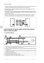
PE
2ES-
1ES+
2ES+
1ES-
a
b
PE
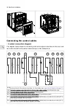
Connecting the control cables
■
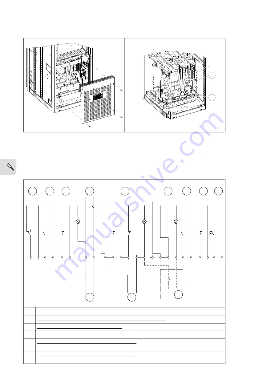
Control connection diagram
The diagram below shows the monitoring and control signal connections for the user, and
the control circuits for the status indicator lamps on the cabinet door.
7
+
N
+24V
x1
x2
-P12.1
12
11
14
-K45
16
15
18
PE
1
2
11
21
9
10
12
14
13
15
22
-X
350
x1
x2
-P13.1
11
12
-Q11.1
-P11.1
x2
x1
5
6
7
8
33
34
-Q11.1
41
42
-Q11.1
-
5
1
2
3
4
6
10
8
9
17
18
19
20
33
34
-Q10.1
21
22
-Q10.1
11
12
-Q10.1
11
12
Terminal block for the control connections. For the location, see
Layout of a DC feeder unit (page 17)
X350
Unit with a common mode filter ([R11.11, R11.12, F45], E208): Overtemperature relay.
K45
Unit with charging switch ([Q10], option F272): Charging switch
Q10.1
Unit with DC switch disconnector ([Q11], option F290): DC switch/disconnector
Q11.1
Unit with DC switch disconnector ([Q11], option F290): Indicator lamp on cabinet door: switch [Q11.1]
interlocking is released. See no. 5 and 4.
P11.1
Unit with DC switch disconnector ([Q11], option F290): Indicator lamp on cabinet door: switch [Q11.1]
disconnected and switch [Q10] disconnected (if included)
P13.1
32 Electrical installation
Содержание ACS880-7107LC DC
Страница 1: ... ABB INDUSTRIAL DRIVES ACS880 7107LC DC feeder unit Hardware manual ...
Страница 2: ......
Страница 4: ......
Страница 8: ...8 ...
Страница 12: ...12 ...
Страница 22: ...22 ...
Страница 36: ...36 ...
Страница 40: ...40 ...
Страница 44: ...44 ...
Страница 50: ...50 ...
Страница 52: ...52 ...
Страница 55: ...Terminal and cable entry data for the power cables Technical data 55 ...

