


154 Start-up
If the Safe torque off functionality is used, check that the STO OUT output on the drive control unit is
chained to the STO inputs of all drives.
If the Safe torque off functionality is not used, check that the STO input on all drives is correctly wired
to +24 V and ground.
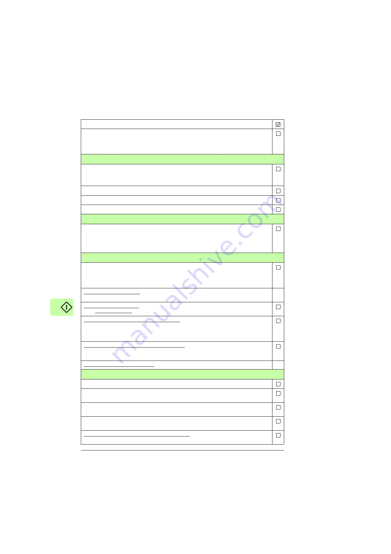
Powering up the auxiliary circuit of the drive
Make sure that it is safe to connect voltage. Ensure that
• nobody is working on the drive or circuits that have been wired from outside into the drive cabinet
• the cover of the motor terminal box is in place.
Close the circuit breakers and/or fuse disconnectors supplying the auxiliary voltage circuits.
Close the cabinet doors.
Close the main breaker of the supply transformer.
Setting up the line-side converter parameters
The line-side converter control program parameters are set at the factory. Normally, there is no need
to change them at the start-up.
For more information on the line-side converter control parameters, see
ACS880 primary control
program firmware manual (3AUA0000085967
[English]) or
ACS880 IGBT supply control program
firmware manual (3AUA0000131562 [English]).
Setting up the motor-side converter parameters, and performing the first start
Set up the motor control program. See the appropriate start-up guide and/or firmware manual. There
is a separate start-up guide only for some control programs.
If you need more information on the use of the control panel, see
ACS-AP-X Assistant control panels
user's manual
(3AUA0000085685 [English]).
For drives with ABB du/dt filter, check that bit 13 of parameter
95.20 HW options word 1
is switched
on.
For drives with ABB sine filter, check that parameter
95.15 Special HW settings
is set to
ABB sine
filter
. For other sine filters, see
Sine filter hardware manual
(3AXD50000016814 [English]).
For drives with a fieldbus adapter module (optional): Set the fieldbus parameters. Activate the
appropriate assistant (if present) in the control program, or see the user’s manual of the fieldbus
adapter module, and the drive firmware manual.
Check that the communication works between the drive and the PLC.
For drives with an encoder interface module (optional): Set the encoder parameters. Activate the
appropriate assistant (if present) in the control program, or see the user’s manual of the encoder
interface module, and the drive firmware manual.
For drives with optional brake chopper, see section
on page
.
On-load checks
Start the motor to perform the ID run.
Check that the cooling fans rotate freely in the right direction, and the air flows upwards. A paper
sheet set on the intake (door) gratings stays. The fans run noiselessly.
Check that the motor starts. stops and follows the speed reference in the correct direction when
controlled with the control panel.
Check that the motor starts. stops and follows the speed reference in the correct direction when
controlled through the customer-specific I/O or fieldbus.
Drives in which the Safe torque off control circuit is in use: Test and validate the operation of the Safe
torque off function. See
Start-up including acceptance test
on page
.
Action
Содержание ACS880-34
Страница 1: ... ABB INDUSTRIAL DRIVES ACS880 34 drive modules 132 to 400 kW 200 to 450 hp Hardware manual ...
Страница 4: ......
Страница 14: ...14 ...
Страница 22: ...22 Safety instructions ...
Страница 28: ...28 Introduction to the manual ...
Страница 42: ...42 Operation principle and hardware description ...
Страница 118: ...118 External control unit ...
Страница 140: ...140 Installation example with full cabling panels option H381 M8 16 Hex 2 5 4 3 1 1 1 1 2 6 7 ...
Страница 152: ...152 Installation checklist ...
Страница 156: ...156 Start up ...
Страница 158: ...158 Fault tracing ...
Страница 174: ...174 Maintenance ...
Страница 202: ...202 Technical data EU Declaration of Conformity Machinery Directive ...
Страница 204: ...204 Technical data ...
Страница 206: ...206 Dimension drawings Standard configuration 3AXD50000038012 ...
Страница 207: ...Dimension drawings 207 Location of power cable connection terminals with options H370 H356 3AXD50000038012 ...
Страница 208: ...208 Dimension drawings Drive module with options 0B051 H356 0H371 3AXD50000038012 ...
Страница 209: ...Dimension drawings 209 Configuration with option H381 3AXD50000323210 ...
Страница 210: ...210 Dimension drawings LCL filter module 3AXD50000206162 ...
Страница 214: ...214 Dimension drawings External control unit 3axd50000011687 ...
Страница 238: ...238 Resistor braking ...
Страница 242: ...242 du dt and sine filters ...
Страница 256: ...Contact us www abb com drives www abb com drivespartners 3AXD50000035191 Rev B EN 2018 09 28 ...


