Note:
Drives with the Emergency stop, stop category 1 function (Q952 or +Q964):
If the user activates the POUS function during the emergency stop deceleration ramp, it
overrides the emergency stop function. This activates the STO function of the drive
immediately and the motor coasts to a stop. For more information on the emergency stop
function, see the appropriate user’s manual.
Note:
ACS880-07 drives, frames nxDXT + nxR8i with a main contactor/breaker (option
+F250/+F255), ACS880-17/17LC/37/37LC drives, frames nxR8i + nxR8i, and ACS880-17/37
drives, frames R8 and R11: When the STO function is activated in the inverter unit, the main
contactor/breaker is opened after a user-defined delay (defined with parameter 94.11, the
default value is 600 s). See the hardware and firmware manuals for more information.
The design principles of the Q957 comply with EN 1037. The STO function complies
with EN/IEC 61800-5-2:2007. For a complete list of related standards and European
directives, see section Related standards and directives.
Operation principle
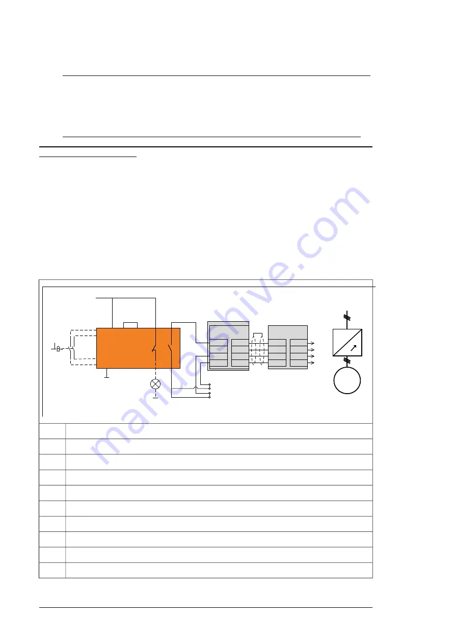
The figure shows a simplified operation principle. For a more detailed description, see the
circuit diagrams delivered with the drive.
-A65
24 VDC+
1
0
-P
-A41
-T11.x
XSTO
XSTO
.OUT
2)
IN2
OUT
SGND
IN1
IN2
OUT
SGND
IN1
IN1
SGND
IN2
SNGD
IN1
SGND
IN2
SNGD
-X51 B
-X52 B
IN1
SGND
IN2
SGND
IN1
SGND
IN2
SGND
OUT1
SGND
OUT2
SGND
OUT1
SGND
OUT2
SGND
-X96 9
-X96 9
1)
-S
M
3~
M
3~
~
~
3)
Main ci rcu it
~
M
3~
~
3)
Main ci rcu it
~
The dashed line in the figure indicates a user-defined installation.
-----
Inverter control unit
A41
POUS safety relay
A65
POUS switch (user-defined)
S
POUS indicator lamp (user-defined)
P
Inverter module(s) under inverter unit T11 (only for R8i)
T11.x
STO terminal block
X969
Reset (automatic)
1)
To parallel inverter modules (if any)
2)
Drive module
3)
16 Option description


