
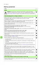

Start-up 65
If the drive is equipped with a main switch/disconnector ([Q1], F253):
Close the main switch/disconnector [Q1].
Close the auxiliary voltage switch [Q21] of the drive supply unit. The converter control unit will be
powered.
Important:
Do not
close the main breaker ([Q1], F255) or the main contactor [Q2] of the
drive supply unit yet! You must not power up the drive DC bus yet.
Setting the parameters
Set DC/DC converter parameters. See chapter Start-up in the
DC/DC converter control program
firmware manual
(3AXD50000024671 [English]).
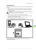
If you need information on the use of the control panel, see
ACX-AP-x assistant control panels user's
manual
(3AUA0000085685 [English]). See also
Drive composer start-up and maintenance PC tool
user’s manual
(3AUA0000094606 [English]).
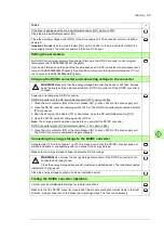
Charging the DC/DC converter and connecting voltage to the converter
WARNING!
Make sure that the energy storage disconnecting device is still open. Always
keep the energy storage disconnected from DC/DC converter until the DC/DC converter is
charged.
Power up and charge the DC/DC converter.
DC/DC converter with the DC switch/disconnector ([Q11], F286):
1. Close the main contactor [Q2] or the main breaker ([Q1], F255) of the drive supply unit.
2. Close the DC/DC converter charging switch [Q10.x]. The DC/DC converter disconnected indicator
[P12.x] goes out.
3. After the Charging OK indicator [P11.x] illuminates, close the DC switch/disconnector [Q11].
4. Open the DC/DC converter charging switch [Q10.x].
Note:
The charging switch must be open before you can start the DC/DC converter.
DC/DC converter without DC switch/disconnector ( = no F286):
1. Close the main contactor [Q2] or the main breaker ([Q1], F255) of the drive supply unit.
The DC/DC converter is energized and gets charged.
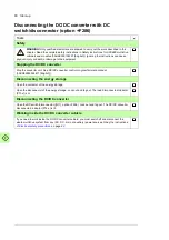
Connecting the energy storage to the DC/DC converter
Set parameter 120.12 Run enable 1 to Off. This makes it sure that the DC/DC converter does not
start automatically or unexpectedly after you connect the energy storage.
Make sure the energy storage voltage is below the DC link voltage.
WARNING!
Do not close the energy storage disconnector if the DC/DC converter is not
connected and ready to use.
Close the energy storage disconnector (customer-installed device). The load disconnected
indicator [P13.x] goes out.
Close the energy storage contactor (customer-installed device).
Testing the DC/DC converter operation
Contact your local ABB representative for testing instructions.
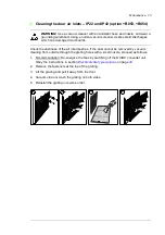
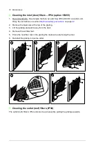
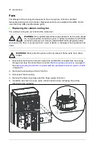
Make sure that the DC/DC converter module and filter module cooling fan rotates freely in the right
direction. A paper sheet set on the intake (door) gratings stays. The fans run noiselessly.
Tasks
Содержание ACS880-1607
Страница 1: ...ABB industrial drives Hardware manual ACS880 1607 DC DC converter units ...
Страница 4: ......
Страница 12: ...12 Introduction to the manual ...
Страница 34: ...34 Mechanical installation ...
Страница 40: ...40 Guidelines for planning electrical installation ...
Страница 52: ...52 Electrical installation ...
Страница 68: ...68 Start up ...
Страница 80: ...80 Maintenance 7 3 4 5 6 ...
Страница 82: ...82 Maintenance 3 4 5 6 7 8 9 9 ...
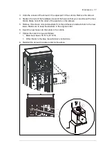
Страница 85: ...Maintenance 85 12 Install and tighten the two screws 10 11 12 ...
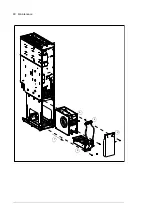
Страница 92: ...92 Maintenance 3 6 4 5 4 7a 7b 7b ...
Страница 93: ...Maintenance 93 9 8 8 10 11 ...
Страница 96: ...96 Maintenance 4 8 6 7 5 3 ...
Страница 97: ...Maintenance 97 9 ...
Страница 118: ...118 Dimensions Dimension drawings Frame 1 R8i bottom cable entry ...
Страница 119: ...Dimensions 119 Frame 1 R8i top cable entry ...
Страница 120: ...120 Dimensions Location and size of input terminals Frame 1 R8i bottom cable entry Frame 1 R8i top cable entry ...
Страница 122: ...www abb com drives www abb com drivespartners 3AXD50000023644 Rev B EN 2017 01 30 Contact us ...


