24 Operation principle and hardware description
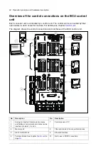
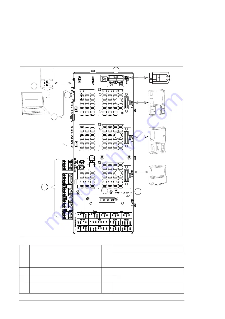
Overview of the control connections on the BCU control
unit
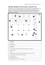
Each converter unit is controlled by a control unit. The control unit is connected by fiber
optic cables to each converter module. For details, see chapter
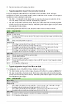
The diagram shows the control connections and interfaces of the BCU control unit.
No.
Description
No.
Description
1
2
3
Analog and digital I/O extension modules
and fieldbus communication modules can be
inserted into slots 1, 2 and 3.
7
Control panel or PC
4
Memory unit
8
Fiber optic links to the converter modules
5
Slot 4 for RDCO-0x
9
Ethernet interface
6
Terminal blocks. See chapter
.
10
Not in use in DC/DC converters.
1
2
3
4
5
6
7
FXX
FXX
FXXX
8
9
10
CLOSE
Содержание ACS880-1607
Страница 1: ...ABB industrial drives Hardware manual ACS880 1607 DC DC converter units ...
Страница 4: ......
Страница 12: ...12 Introduction to the manual ...
Страница 34: ...34 Mechanical installation ...
Страница 40: ...40 Guidelines for planning electrical installation ...
Страница 52: ...52 Electrical installation ...
Страница 68: ...68 Start up ...
Страница 80: ...80 Maintenance 7 3 4 5 6 ...
Страница 82: ...82 Maintenance 3 4 5 6 7 8 9 9 ...
Страница 85: ...Maintenance 85 12 Install and tighten the two screws 10 11 12 ...
Страница 92: ...92 Maintenance 3 6 4 5 4 7a 7b 7b ...
Страница 93: ...Maintenance 93 9 8 8 10 11 ...
Страница 96: ...96 Maintenance 4 8 6 7 5 3 ...
Страница 97: ...Maintenance 97 9 ...
Страница 118: ...118 Dimensions Dimension drawings Frame 1 R8i bottom cable entry ...
Страница 119: ...Dimensions 119 Frame 1 R8i top cable entry ...
Страница 120: ...120 Dimensions Location and size of input terminals Frame 1 R8i bottom cable entry Frame 1 R8i top cable entry ...
Страница 122: ...www abb com drives www abb com drivespartners 3AXD50000023644 Rev B EN 2017 01 30 Contact us ...

