
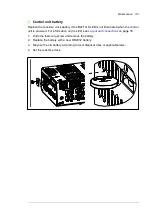

102 Maintenance
LEDs and other status indicators
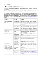
This section instructs how to interpret the status indications of the ACS880-1607 DC/DC
converter unit.
Warnings and faults reported by the control program are displayed on the control panel on
the cabinet door. For further information, see the firmware manual.
The ACS-AP-x control panel has a status LED. The control panel mounting platform has
two LEDs - a red and a green one. The DC/DC converter module has three LEDs. The
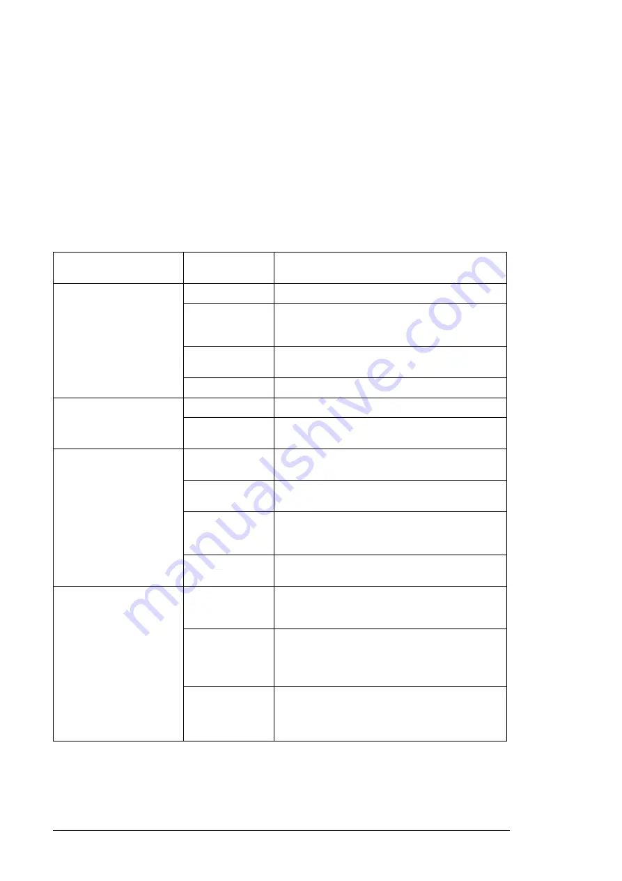
cabinet has from one to three door lamps. For their indications, see the following table. For
the indications of the 7-segment display of the control unit, see
Location
LED and
indicators
Indication
ACS-AP-x control panel
(status LED)
Continuous green
The DC/DC converter unit is functioning normally.
Flickering green
Data is transferred between the PC tool and DC/DC
converter unit through the USB connection of the
control panel.
Blinking green
There is an active warning in the DC/DC converter
unit.
Continuous red
There is an active fault in the DC/DC converter unit.
Control panel mounting
platform (with the control
panel removed)
Red
There is an active fault in the DC/DC converter unit.
Green
Power supply for the control board of the DC/DC
converter unit is ok.
DC/DC converter module
FAULT
(continuous red)
There is an active fault in the DC/DC converter
module.
ENABLE / STO
(continuous green)
The DC/DC converter module is ready for use.
ENABLE / STO
(continuous
yellow)
Safe torque off connectors are de-energized.
POWER OK
(continuous green)
Supply voltage on the board is OK (> 21 V).
Cabinet door lamps
Note:
When the white
lamps are on, the DC/DC
converter is disconnected
from both the DC bus and
the energy storage.
Charging OK
indicator (green)
The DC bus of the converter modules is charged.
The unit is ready for connection to the common DC
bus.
DC/DC converter
disconnected
(white)
The DC/DC converter unit is disconnected from the
main DC bus.
Note
: Auxiliary voltages are to be disconnected
separately.
Load
disconnected
indicator (white)
The disconnector of the energy storage is switched
off. For more information, see
Содержание ACS880-1607
Страница 1: ...ABB industrial drives Hardware manual ACS880 1607 DC DC converter units ...
Страница 4: ......
Страница 12: ...12 Introduction to the manual ...
Страница 34: ...34 Mechanical installation ...
Страница 40: ...40 Guidelines for planning electrical installation ...
Страница 52: ...52 Electrical installation ...
Страница 68: ...68 Start up ...
Страница 80: ...80 Maintenance 7 3 4 5 6 ...
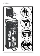
Страница 82: ...82 Maintenance 3 4 5 6 7 8 9 9 ...
Страница 85: ...Maintenance 85 12 Install and tighten the two screws 10 11 12 ...
Страница 92: ...92 Maintenance 3 6 4 5 4 7a 7b 7b ...
Страница 93: ...Maintenance 93 9 8 8 10 11 ...
Страница 96: ...96 Maintenance 4 8 6 7 5 3 ...
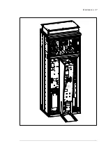
Страница 97: ...Maintenance 97 9 ...
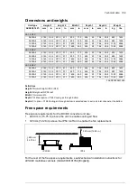
Страница 118: ...118 Dimensions Dimension drawings Frame 1 R8i bottom cable entry ...
Страница 119: ...Dimensions 119 Frame 1 R8i top cable entry ...
Страница 120: ...120 Dimensions Location and size of input terminals Frame 1 R8i bottom cable entry Frame 1 R8i top cable entry ...
Страница 122: ...www abb com drives www abb com drivespartners 3AXD50000023644 Rev B EN 2017 01 30 Contact us ...


