Resistor braking 161
15
Resistor braking
Contents of this chapter
This chapter describes how to select, protect and wire brake choppers and resistors. The
chapter also contains the technical data.
Operation principle and hardware description
The dive can be equipped with optional built-in brake chopper (+D150). Brake resistors
are available as add-on kits.
The brake chopper handles the energy generated by a decelerating motor. The chopper
connects the brake resistor to the intermediate DC circuit whenever the voltage in the
circuit exceeds the limit defined by the control program. Energy consumption by the
resistor losses lowers the voltage until the resistor can be disconnected.
Planning the braking system
Selecting the default brake circuit components
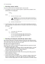
1. Calculate the maximum power generated by the motor during braking (
P
max
).
2. Select a suitable drive, brake chopper and brake resistor combination for the
application from the rating table. The braking power of the chopper
must be greater or
equal than the maximum power generated by the motor during the braking.
3. Check the resistor selection. The energy generated by the motor during a 400-second
period must not exceed the resistor heat dissipation capacity
E
R
.
Note
: If the
E
R
value is not sufficient, it is possible to use a four-resistor assembly in
which two standard resistors are connected in parallel, two in series. The
E
R
value of
the four-resistor assembly is four times the value specified for the standard resistor.
Содержание ACS880-07XT Series
Страница 1: ...ABB industrial drives Hardware manual ACS880 07XT drives 400 to 1200 kW ...
Страница 4: ......
Страница 12: ...12 ...
Страница 20: ...20 Safety instructions ...
Страница 26: ...26 Introduction to the manual ...
Страница 47: ...Mechanical installation 47 Moving the crate with a forklift Free width for fork tines 750 mm 29 5 ...
Страница 54: ...54 Mechanical installation ...
Страница 89: ...Electrical installation 89 PE 11 8 4 9 11 ...
Страница 94: ...94 Electrical installation ...
Страница 110: ...110 Start up Test and validate the operation of Prevention of unexpected start with FSO xx option Q950 Action ...
Страница 112: ...112 Fault tracing ...
Страница 123: ...Maintenance 123 5 6 7 ...
Страница 124: ...124 Maintenance 8 10 9 ...
Страница 126: ...126 Maintenance 6 5 4 ...
Страница 127: ...Maintenance 127 9 8 7 ...
Страница 128: ...128 Maintenance 12 11 10 ...
Страница 149: ...Dimensions 149 Dimension drawing examples Frame 2 R11 R10 with brake chopper ...
Страница 150: ...150 Dimensions Frame 2 R11 R10 without brake chopper ...
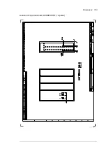
Страница 153: ...Dimensions 153 Location of input terminals ACS880 07XT 12 pulse ...
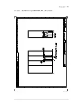
Страница 154: ...154 Dimensions Location of output terminals ACS880 07XT R10 with du dt ...
Страница 155: ...Dimensions 155 Location of output terminals ACS880 07XT R10 without du dt ...
Страница 156: ...156 Dimensions Location of output terminals ACS880 07XT R11 with du dt ...
Страница 157: ...Dimensions 157 Location of output terminals ACS880 07XT R11 without du dt ...
Страница 158: ...158 Dimensions Location of PE terminals ACS880 07XT ...
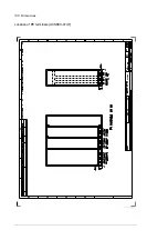
Страница 159: ...Dimensions 159 Location of resistor terminals ACS880 07XT R10 ...
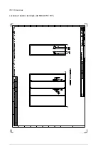
Страница 160: ...160 Dimensions Location of resistor terminals ACS880 07XT R11 ...
Страница 168: ...www abb com drives www abb com drivespartners 3ABD00043579 Rev C EN 2018 01 01 Contact us ...


