background image

152   Dimensions

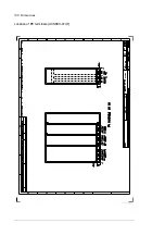
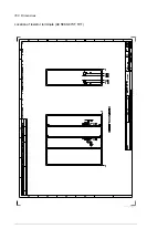
Location of input terminals 

(

ACS880-07XT-1310A-5, ACS880-07XT-1320A-7, ACS880-

07XT-1330A-3, ACS880-07XT-1610A-3, ACS880-07XT-1610A-5

)

Содержание ACS880-07XT Series

Страница 1: ...ABB industrial drives Hardware manual ACS880 07XT drives 400 to 1200 kW ...

Страница 2: ...0 to 1200 kW hardware manual 3AXD50000025169 ACS AP X assistant control panels user s manual 3AUA0000085685 Drive firmware manuals and guides ACS880 primary control program firmware manual 3AUA0000085967 Quick start up guide for ACS880 drives with primary control program 3AUA0000098062 ...

Страница 3: ...l ACS880 07XT drives 400 to 1200 kW 3ABD00043579 Rev C EN EFFECTIVE 2018 01 01 2018 ABB Drive All Rights Reserved 1 Safety instructions 4 Mechanical installation Table of contents 6 Electrical installation 9 Start up ...

Страница 4: ......

Страница 5: ...n flowchart 23 Terms and abbreviations 24 Safety data SIL PL 25 3 Operation principle and hardware description Contents of this chapter 27 Product overview 27 Overview circuit diagram of the drive 28 12 pulse connection option A004 29 Cabinet line up and layout examples 30 Example Frame R11 30 Overview of power and control connections 32 Door switches and lights 34 Main disconnecting device Q1 1 3...

Страница 6: ... and roof wall marine units 52 Miscellaneous 53 Cable duct in the floor below the cabinet 53 5 Guidelines for planning the electrical installation Contents of this chapter 55 Selecting the supply disconnecting device 56 European Union 56 Other regions 56 Selecting the main contactor 56 Examining the compatibility of the motor and drive 56 Protecting the motor insulation and bearings 57 Requirement...

Страница 7: ...mplementing the Power loss ride through function 71 Using power factor compensation capacitors with the drive 71 Implementing a safety switch between the drive and the motor 71 Using a contactor between the drive and the motor 72 Implementing a bypass connection 72 Example bypass connection 73 Switching the motor power supply from drive to direct on line 73 Switching the motor power supply from di...

Страница 8: ...ve What this chapter contains 95 General 95 Control unit layout and connections 96 Default I O diagram of the control unit A41 98 External power supply for the control unit XPOW 99 DI6 as a PTC sensor input 99 AI1 or AI2 as a Pt100 Pt1000 or KTY84 sensor input 100 DIIL input 100 Drive to drive link XD2D 100 Safe torque off XSTO XSTO OUT 101 SDHC memory card slot 101 Control unit connector data 102...

Страница 9: ...left module 125 Capacitors 129 Reforming the capacitors 129 Control panel 129 Replacing the battery 129 Cleaning 129 Control units 130 BCU control unit types 130 Memory unit 130 Control unit battery 131 Reduced run 132 Starting reduced run operation 132 Resuming normal operation 132 12 Technical data Contents of this chapter 133 Ratings 133 Ambient temperature derating 134 Altitude derating 135 Hi...

Страница 10: ... Location of output terminals ACS880 07XT R10 with du dt 154 Location of output terminals ACS880 07XT R10 without du dt 155 Location of output terminals ACS880 07XT R11 with du dt 156 Location of output terminals ACS880 07XT R11 without du dt 157 Location of PE terminals ACS880 07XT 158 Location of resistor terminals ACS880 07XT R10 159 Location of resistor terminals ACS880 07XT R11 160 14 Resisto...

Страница 11: ...ure 164 Start up 164 Technical data 165 Ratings 165 SAFUR resistors 165 Dimensions and weights 166 Ordering codes 166 Terminals and cable lead through data 166 Further information Product and service inquiries 167 Product training 167 Providing feedback on ABB Drives manuals 167 Document library on the Internet 167 ...

Страница 12: ...12 ...

Страница 13: ...mage to the equipment They also tell you how to prevent the danger Notes draw attention to a particular condition or fact or give information on a subject The manual uses these warning symbols Electricity warning tells about hazards from electricity which can cause injury or death or damage to the equipment General warning tells about conditions other than those caused by electricity which can cau...

Страница 14: ...he module does not topple over when you move it on the floor Open the support legs by pressing each leg a little down 1 2 and turning it aside Whenever possible secure the module also with chains Do not tilt the drive module A It is heavy and its center of gravity is high The module overturns from a sideways tilt of 5 degrees Do not leave the module unattended on a sloping floor Do not use the mod...

Страница 15: ...operation Obey the panel builder s instructions Before you adjust the drive operation limits make sure that the motor and all driven equipment can operate throughout the set operation limits Before you activate the automatic fault reset or automatic restart functions of the drive control program make sure that no dangerous situations can occur These functions reset the drive automatically and cont...

Страница 16: ...not possible Lock the disconnectors to open position and attach a warning notice to them Disconnect any external power sources from the control circuits before you do work on the control cables After you disconnect the drive always wait for 5 minutes to let the intermediate circuit capacitors discharge before you continue 3 Protect any other energized parts in the work location against contact 4 T...

Страница 17: ... dangerous voltage when the input power is on regardless of whether the motor is running or not The DC bus and brake resistor terminals UDC UDC R and R are at a dangerous voltage External wiring can supply dangerous voltages to the terminals of relay outputs XRO1 XRO2 and XRO3 The Safe torque off function does not remove the voltage from the main and auxiliary circuits The function is not effectiv...

Страница 18: ...of the grounding conductors is sufficient See section Selecting the power cables on page 71 Obey the local regulations Connect the power cable shields to protective earth PE of the drive to make sure of personnel safety Make a 360 grounding of the power and control cable shields at the cable entries to suppress electromagnetic disturbances In a multiple drive installation connect each drive separa...

Страница 19: ... during work Make sure that no other system like hydraulic crawling drives can rotate the motor directly or through any mechanical connection like felt nip rope etc Measure that the installation is de energized Use a multimeter with an impedance of at least 1 Mohm Make sure that the voltage between the drive output terminals T1 U2 T2 V2 T3 W2 and the grounding PE busbar is close to 0 V Make sure t...

Страница 20: ...20 Safety instructions ...

Страница 21: ...hematic symbols The manual is written for readers worldwide Both SI and imperial units are shown Contents of the manual This manual contains the instructions and information for the basic drive configuration The chapters of the manual are briefly described below Safety instructions gives safety instructions for the installation start up operation and maintenance of the drive Introduction to the ma...

Страница 22: ...ements provisions for fulfilling the requirements for CE and other markings Dimensions contains example dimension drawings of the drive Safe torque off function describes the Safe torque off function of the drive and gives instructions on its implementation Resistor braking describes selection protection and wiring of optional brake choppers and resistors The chapter also contains technical data R...

Страница 23: ... drive Mechanical installation page 43 If the drive has been non operational for more than one year the DC link capacitors need to be reformed page 129 Route the cables Routing the cables page 85 Check the insulation of the supply cable the motor and the motor cable Checking the insulation of the assembly page 75 If the drive is about to be connected to an IT ungrounded system check that the drive...

Страница 24: ...NA 11 Optional Ethernet adapter module for EtherNet IP Modbus TCP and PROFINET IO protocols FENA 21 Optional Ethernet adapter module for EtherNet IP Modbus TCP and PROFINET IO protocols 2 port FEPL 01 Optional Ethernet POWERLINK adapter module FIO 01 Optional digital I O extension module FIO 11 Optional analog I O extension module FLON 01 Optional LonWorks adapter module FPBA 01 Optional PROFIBUS ...

Страница 25: ...terval under stated conditions PFD IEC 61508 Probability of failure on demand PFHD IEC 61508 Probability of dangerous failures per hour PL EN ISO 13849 1 Performance level Levels a e correspond to SIL SC IEC 61508 Systematic capability SFF IEC 61508 Safe failure fraction SIL IEC 61508 Safety integrity level 1 3 SILCL IEC EN 62061 Maximum SIL level 1 3 that can be claimed for a safety function or s...

Страница 26: ...26 Introduction to the manual ...

Страница 27: ...fly describes the operation principle and construction of the drive Product overview The ACS880 07XT is an air cooled cabinet installed drive for controlling asynchronous AC induction motors permanent magnet synchronous motors and AC induction servomotors The drive consists of two drive modules ACS880 04 P943 and a separate control unit ...

Страница 28: ...Converts direct current and voltage to alternating current and voltage 5 Brake chopper option D150 Conducts the surplus energy from the intermediate circuit of the drive to the brake resistor when necessary The chopper operates when the DC link voltage exceeds a certain maximum limit The voltage rise is typically caused by deceleration braking of a high inertia motor L1 U1 L2 V1 L3 W1 T1 U2 T2 V2 ...

Страница 29: ...ics which remarkably reduces the harmonic distortion of the line current and the conducted emissions 12 pulse connection requires a three winding transformer or two separate transformers There is a 30 degree phase shift between the two 6 pulse supply lines which are connected to different supply modules through electrically separate switching equipment No Description 1 Supply transformer See secti...

Страница 30: ...ubicle ICU Contains control electronics customer I O connections the power input cable terminals and switchgear B Module cubicle Contains the R11 module C Output cubicle Contains the du dt option and output ternimals for motor D Module cubicle Contains the R11 module 1 Main switch disconnector Q1 1 2 Door switches and lights 3 Drive control panel A C D 1 3 2 B ...

Страница 31: ...d throughs PE busbar behind grid 2 Input terminals behind grid 3 Main switch disconnector Q1 1 4 AC fuses behind swing out door 5 Main contactor Q2 1 optional behind swing door 6 Control unit BCU 02 7 Output cubicle cooling fan 8 Module 9 Bus bar 10 Output terminals 2 3 4 5 6 1 7 8 9 10 8 ...

Страница 32: ...in the auxiliary control cabinet of the drive 9 Fiber optic link to each inverter module Similarly each supply module is connected to the supply control unit by fiber optic cables 10 Terminal blocks for customer connections installed in the drive cabinet For the locations 11 Rectifier L1 L2 L3 PE U2 V2 W2 M 3 L1 L2 L3 PE Fxx Slots 1 2 and 3 1 7 6 10 4 2 3 Slot 4 5 X205 X12 X13 8 Control unit A41 V...

Страница 33: ...Operation principle and hardware description 33 12 Bus bar link 13 Inverter 14 Optional brake chopper D150 and resistors D151 ...

Страница 34: ...OP RESET Emergency stop reset push button with options Q951 Q952 Q963 and Q964 6 EARTH FAULT Ground earth fault light with option Q954 7 Reserved for application engineered equipment 8 EMERGENCY STOP Emergency stop push button with options Q951 Q952 Q963 and Q964 The layout depends on the options selected 1 2 3 4 5 6 7 8 OFF OFF Run enable signal off starting the supply unit not allowed ON Run ena...

Страница 35: ...connector to the 0 OFF position or rack out the main breaker whichever device is installed WARNING The main disconnecting device does not isolate the input power terminals AC voltage meters or the auxiliary voltage circuit from the power line To isolate the auxiliary voltage circuit open the auxiliary voltage switch Q21 To isolate the input power terminals and AC voltage meters open the main break...

Страница 36: ...l program The control panel can be removed by pulling it forward from the top edge and reinstalled in reverse order For the use of the control panel see ACS AP assistant control panel user s manual 3AUA0000085685 English and the firmware manual Control by PC tools There is a USB connector on the front of the panel that can be used to connect a PC to the drive When a PC is connected to the control ...

Страница 37: ...ee of protection of IP42 The air inlet gratings are covered with a metallic mesh between the inner metallic grating and the outer plastic grating IP54 pending This option provides the degree of protection of IP54 It provides the cabinet air inlets with filter housings containing folded board air filter mats between the inner metallic grating and the outer plastic grating An additional fan on the c...

Страница 38: ...optional module control wires directly to the modules Thermistor relays options L505 2L505 The thermistor relay is used for the overtemperature supervision of motors equipped with PTC thermistors When the motor temperature rises to the thermistor wake up level the thermistor resistance increases sharply The relay detects the change and indicates motor overtemperature through its auxiliary contacts...

Страница 39: ...e three sensors measure the temperature of the motor windings and two sensors the temperature of the bearings The sensor resistance increases linearly as the temperature rises The relay releases at an adjustable wake up level and indicates motor overtemperature through its change over contact The relay provides connection terminals for one Pt100 temperature sensor and terminals of one normally ope...

Страница 40: ...rotection 5 Ratings See section Ratings on page 133 section Electrical power network specification on page 139 and section Motor connection data on page 139 6 Short circuit withstand strength section Electrical power network specification on page 139 7 Valid markings 8 Serial number The first digit of the serial number refers to the manufacturing plant The next four digits refer to the unit s manu...

Страница 41: ...ilable for ACS880 04XT xxxx 3 and 5 types only E205 du dt output filter Line options F250 Line contactor Cabinet equipment G300 Cabinet and module heating elements external supply G307 Terminals for connecting external control voltage 230 V AC or 115 V AC eg UPS Motor cable options H366 Common output for motor need selecting E205 Fieldbus adapters K451 FDNA 01 DeviceNet adapter module K454 FPBA 01...

Страница 42: ...31 3 application programmability Specialties P902 Customized P904 Extended warranty P912 Seaworthy packaging P913 Special color P929 Container packaging Safety functions Q954 Earth fault monitoring unearthed mains Q951 Emergency stop category 0 with safety relays by opening the main breaker contactor Q952 Emergency stop category 1 with safety relays by opening the main breaker contactor Q963 Emerg...

Страница 43: ...ive to enable cooling air flow service and maintenance The floor that the unit is installed on is of non flammable material as smooth as possible and strong enough to support the weight of the unit Check the floor flatness with a spirit level The maximum allowed deviation from the surface level is 5 mm in every 3 meters Level the installation site if necessary as the cabinet is not equipped with a...

Страница 44: ...rs torque wrench set of wrenches or sockets Checking the delivery The drive delivery contains drive cabinet line up optional modules if ordered installed onto the control unit at the factory appropriate drive and optional module manuals delivery documents Check that there are no signs of damage Before attempting installation and operation check the information on the type designation labels of the...

Страница 45: ...aging the cabinet surfaces and door devices When you are using a pallet truck check its load capacity before you move the drive The drive cabinet is to be moved in the upright position The center of gravity of the cabinet is high Be therefore careful when moving the unit Avoid tilting Moving the drive in its packaging Lifting the crate with a forklift ...

Страница 46: ...46 Mechanical installation Lifting the crate with a crane max 20 Position each sling as close to a transverse board as possible We recommend the use of transverse spreader bars Lifting point ...

Страница 47: ...Mechanical installation 47 Moving the crate with a forklift Free width for fork tines 750 mm 29 5 ...

Страница 48: ...is mounted onto the transport pallet by undoing the fastening screws 4 Remove the plastic wrapping Moving the unpacked drive cabinet Lifting the cabinet with a crane Lift the drive cabinet using its lifting eyes The lifting eyes can be removed after the cabinet is in its final position but their mounting holes must be blocked to retain the degree of protection Note The minimum allowed height of th...

Страница 49: ...ifting the unit with a crane forklift pallet truck or jack Moving the cabinet on its back Support the cabinet from below alongside the cubicle seams Final placement of the cabinet Move the cabinet into its final position with a slate bar spud bar Place a piece of wood between the edge of the cabinet and the bar to protect the cabinet frame Cabinet back panel Support ...

Страница 50: ...t requires 320 mm 12 28 of free space above the filter compartment Leave some space w at the side where the cabinet outmost hinges are to allow the doors to open sufficiently The doors must open 120 to allow supply or inverter module replacement Note 1 Any height adjustment must be done before fastening the units or shipping splits together Height adjustment can be done by using metal shims betwee...

Страница 51: ... recommended maximum distance between the clamps in the front edge is 800 mm 31 5 2 If floor mounting at the back is not possible fasten the top of the cabinet to the wall with L brackets not included in the delivery bolted to the lifting bar fastening holes 1 Fasten the cabinet to the floor through the bottom fastening holes with M10 to M12 3 8 to 1 2 bolts The recommended maximum distance betwee...

Страница 52: ...to the floor and roof wall as follows 1 Bolt the unit to the floor through the holes in each flat bar at the base of the cabinet using M10 or M12 screws 2 If there is not enough room behind the cabinet for installation clamp the rear ends of the flat bars 3 Remove the lifting lugs and bolt the fastening brackets into the lifting lug holes Fasten the top of the cabinet to the rear wall and or roof ...

Страница 53: ...the two 50 mm wide transverse sections which the floor must carry Prevent the cooling air flow from the cable duct to the cabinet by bottom plates To ensure the degree of protection for the cabinet use the original bottom plates delivered with the unit With user defined cable entries take care of the degree of protection fire protection and EMC compliance 500 19 68 50 1 97 500 19 68 50 1 97 ...

Страница 54: ...54 Mechanical installation ...

Страница 55: ...ons cable routing and way of operation for the drive system Limitation of liability The installation must always be designed and made according to applicable local laws and regulations ABB does not assume any liability whatsoever for any installation which breaches the local laws and or other regulations Furthermore if the recommendations given by ABB are not obeyed the drive can experience proble...

Страница 56: ...eously Select the contactor according to nominal voltage of the drive and the drive or basic module current Examining the compatibility of the motor and drive Use an asynchronous AC induction motor permanent magnet motor AC induction servomotor or ABB synchronous reluctance motor SynRM motor with the drive Several induction motors can be connected at a time Select the motor size and drive type fro...

Страница 57: ...operties of the motor cable and the terminals The increased voltage can cause additional stress on the motor and motor cable insulation Modern variable speed drives with their fast rising voltage pulses and high switching frequencies can generate current pulses that flow through the motor bearings This can gradually erode the bearing races and rolling elements Optional du dt filters protect motor ...

Страница 58: ...size NEMA 580 ABB motors Random wound M2_ M3_and M4_ UN 500 V Standard N N CMF 1 500 V UN 600 V Standard N du dt N du dt CMF or Reinforced N N CMF 1 600 V UN 690 V cable length 150 m Reinforced N du dt N du dt CMF 600 V UN 690 V cable length 150 m Reinforced N N CMF 1 Form wound HX_and AM_ 380 V UN 690 V Standard N CMF PN 500 kW N CMF 1 PN 500 kW N du dt CMF Old form wound HX_and modular 380 V UN ...

Страница 59: ...lters are needed in the applied drive operation range 1 also du dt filter is required at the output of the basic drive modules if the motor cable length is less than 20 meters before connecting the motor cables together Abbreviation Definition UN Nominal AC line voltage ÛLL Peak line to line voltage at motor terminals which the motor insulation must withstand PN Motor nominal power du dt du dt fil...

Страница 60: ...large part of its operation time Example Motor insulation requirement for a 400 V AC line voltage application must be selected as if the drive were supplied with 480 V Additional requirements for ABB high output and IP23 motors The rated output power of high output motors is higher than what is stated for the particular frame size in EN 50347 2001 This table shows the requirements for ABB random w...

Страница 61: ...ame size IEC 400 134 hp PN 469 hp or NEMA 500 frame size NEMA 580 UN 420 V Standard ÛLL 1300 V N CMF 1 420 V UN 500 V Standard ÛLL 1300 V N du dt CMF or Reinforced ÛLL 1600 V 0 2 microsecond rise time N CMF 1 500 V UN 600 V Reinforced ÛLL 1600 V du dt N CMF or Reinforced ÛLL 1800 V N CMF 1 600 V UN 690 V Reinforced ÛLL 1800 V N du dt CMF Reinforced ÛLL 2000 V 0 3 microsecond rise time N CMF 1 If t...

Страница 62: ...ppropriate diagram Multiply the values by the nominal supply voltage UN and substitute into equation t 0 8 ÛLL du dt Additional note for sine filters Sine filters protect the motor insulation system Therefore the du dt filter can be replaced with a sine filter The peak phase to phase voltage with the sine filter is approximately 1 5 UN Additional note for common mode filters Common mode filter is ...

Страница 63: ...motor cable shields 360 at both ends Keep the motor cable and its PE pigtail twisted shield as short as possible to reduce high frequency electromagnetic emissions Note When continuous metal conduit is employed shielded cable is not required The conduit must have bonding at both ends A four conductor system is allowed for input cabling but shielded symmetrical cable is recommended Compared to a fo...

Страница 64: ...put voltage and the load current of the drive Drive type ACS880 07XT IEC1 input and motor cabling Cabling per basic module Common cabling for the basic modules Cu cable type Al cable type Cu cable type Al cable type mm2 mm2 mm2 mm2 UN 400 V 1010A 3 3 3 120 3 3 185 4 3 185 5 3 240 1190A 3 3 3 150 3 3 240 4 3 240 6 3 240 1330A 3 3 3 185 4 3 185 5 3 240 6 3 240 1610A 3 3 3 240 4 3 240 6 3 240 7 3 240...

Страница 65: ... allowance Symmetrical shielded cable with three phase conductors and a concentric PE conductor as shield A separate PE conductor is required if the shield does not agree with the requirements of IEC 61439 1 Symmetrical shielded cable with three phase conductors and symmetrically constructed PE conductor and a shield The PE conductor must agree with the requirements of IEC 61439 1 A four conductor...

Страница 66: ...er the emission level and bearing currents Armored cable shielded power cable Six conductor 3 phases and 3 ground type MC continuous corrugated aluminum armor cable with symmetrical grounds is available from the following suppliers trade names in parentheses Anixter Wire Cable Philsheath BICC General Corp Philsheath Rockbestos Co Gardex Oaknite CLX Shielded power cables are available from Belden L...

Страница 67: ...length and type In remote use the cable connecting the control panel to the drive must not exceed three meters 10 ft Cable type shielded CAT 5e or better Ethernet patch cable with RJ 45 ends Routing the cables Route the motor cable away from other cable routes Motor cables of several drives can be run in parallel when installed next to each other The motor cable input power cable and control cable...

Страница 68: ...motor cable To minimize the emission level when safety switches contactors connection boxes or similar equipment are installed on the motor cable between the drive and the motor European Union Install the equipment in a metal enclosure with 360 degree grounding for the shields of both the incoming and outgoing cable or connect the shields of the cables otherwise together Drive Motor cable Power ca...

Страница 69: ...erating principle and construction of circuit breakers independent of the manufacturer hot ionized gases can escape from the breaker enclosure in case of a short circuit To ensure safe use pay special attention to the installation and placement of the breakers Obey the manufacturer s instructions Protecting the motor and motor cable in short circuits The drive protects the motor cable and motor in...

Страница 70: ...drive against ground faults The drive is equipped with an internal ground fault protective function to protect the drive against ground faults in the motor and motor cable in TN grounded networks This is not a personal safety or a fire protection feature The ground fault protective function can be disabled with a parameter refer to the firmware manual Measures for protection in case of direct or i...

Страница 71: ...s or harmonic filters to the motor cables between the drive and the motor They are not meant to be used with AC drives and can cause permanent damage to the drive or themselves If there are power factor compensation capacitors in parallel with the three phase input of the drive 1 Do not connect a high power capacitor to the power line while the drive is connected The connection will cause voltage ...

Страница 72: ...motor control mode is in use never open the output contactor while the drive controls the motor The DTC motor control operates extremely fast much faster than it takes for the contactor to open its contacts When the contactor starts opening while the drive controls the motor the DTC control will try to maintain the load current by immediately increasing the drive output voltage to the maximum This...

Страница 73: ...ol mode 2 Open the main contactor of the drive with S11 3 Switch the motor power supply from the drive to direct on line with S40 4 Wait for 10 seconds to allow the motor magnetization to die away 5 Start the motor with S41 Q1 Drive main switch Q4 Bypass circuit breaker K1 Drive main contactor K4 Bypass contactor K5 Drive output contactor S11 Drive main contactor on off control S40 Motor power sup...

Страница 74: ...contactors motors cause voltage transients when switched off The relay contacts on the drive control unit are protected with varistors 250 V against overvoltage peaks In spite of this it is highly recommended that inductive loads are equipped with noise attenuating circuits varistors RC filters AC or diodes DC in order to minimize the EMC emission at switch off If not suppressed the disturbances m...

Страница 75: ...structions can cause injury or death Checking the insulation of the assembly Drive Do not make any voltage tolerance or insulation resistance tests on any part of the drive as testing can damage the drive Every drive has been tested for insulation between the main circuit and the chassis at the factory Also there are voltage limiting circuits inside the drive which cut down the testing voltage aut...

Страница 76: ...s Note Moisture inside the motor casing will reduce the insulation resistance If moisture is suspected dry the motor and repeat the measurement Checking the compatibility with IT ungrounded systems EMC filter E201 is not suitable for use in an IT ungrounded system If the drive is equipped with filter E201 it can not be used in an IT ungrounded system WARNING If a drive with EMC filter E201 is inst...

Страница 77: ...ol cables as described in section Routing the control cables inside the cabinet 4 Connect the control cables as described starting Grounding the outer shields of the control cables at the cabinet lead through Ground the outer shields of all control cables 360 degrees at the EMI conductive cushions as follows 1 Loosen the tightening screws of the EMI conductive cushions and pull the cushions apart ...

Страница 78: ...cient IP and EMC protection can be achieved However if very many control cables come to one cabinet plan the installation beforehand as follows 1 Make a list of the cables coming to the cabinet 2 Sort the cables going to the left into one group and the cables going to the right into another group to avoid unnecessary crossing of cables inside the cabinet 3 Sort the cables in each group according t...

Страница 79: ... terminal block X504 option L504 Connect the inner twisted pair shields and all separate grounding wires to the grounding clamps below the control unit The drawing below represents a drive with additional I O terminal block option L504 Without the block the grounding is made the same way Notes Do not ground the outer shield of the cable here since it is grounded at the lead through Keep any signal...

Страница 80: ... options Q951 Q952 Q963 Q964 Connect external emergency stop push buttons according to the circuit diagrams delivered with the drive Wiring the starter for auxiliary motor fan options M602 M610 Connect the power supply wires for the auxiliary motor fan to terminal blocks X601 X610 according to the circuit diagrams delivered with the drive 1 2 PE 4 5 N L X91 PE 1 1 Internal wiring of UPS supervisio...

Страница 81: ...ing see the circuit diagram delivered with the drive 1 2 3 4 5 6 7 8 9 10 11 12 25 26 27 28 X506 T T 1 n PTC 6 5 1 n PTC 1 PTC sensors monitored by relay K74 RG R1 R2 RN 1 5 kohm 2 External reset for relay K74 to be bridged for autoreset functionality 3 PTC sensors monitored by relay K75 RG R1 R2 RN 1 5 kohm 4 External reset for relay K75 to be bridged for autoreset functionality 5 Overheat indica...

Страница 82: ...e circuit diagram delivered with the drive 1 2 3 4 5 6 7 8 9 10 11 12 13 14 15 16 17 18 19 20 21 22 23 24 25 26 27 28 29 30 X506 T 1 Pt100 2 1 T T T T T T T 3 1 Internal wiring of the windings overheat modules 1 3 overtemperature contact open 2 Internal wiring of the bearings overheat module 4 and 5 overtemperature contact open 3 Internal wiring of the windings overheat modules 6 8 overtemperature...

Страница 83: ...recommend to connect Alarm 1 for drive tripping and Alarm 2 for alarm signals in order to avoid unnecessary trippings due to the ground fault monitor self testing with Alarm 2 1 2 PE 4 5 N L X91 PE 1 Internal wiring of the cabinet heater heater off fault contact open 1 1 2 3 4 X954 Alarm 1 Alarm 2 1 Internal wiring Ground fault alarm 1 No ground fault contact closed Contact load capacity 250 V AC ...

Страница 84: ...l parallel connected modules are to be cabled separately to the motor 360 earthing is to be used at cable lead throughs Motor cable should same and above 20m WARNING The cabling from all inverter modules to the motor must be physically identical considering cable type cross sectional area and length U2 V2 W2 PE U2 V2 W2 M 3 U1 W1 V1 PE Module output Module output PE U2 V2 W2 U2 V2 W2 M 3 U1 W1 V1 ...

Страница 85: ...s in section Precautions before electrical work before you start the work 2 Open the door of the common motor terminal or sine filter cubicle and remove the shrouding 3 Lead the cables into the cubicle Make the 360 earthing arrangement at the cable entry as shown 4 Cut the cables to suitable length Strip the cables and conductors 5 Twist the cable screens into bundles and connect the bundles to th...

Страница 86: ...ny shrouding removed earlier and close the cubicle doors 9 At the motor connect the cables according to instructions from the motor manufacturer Pay special attention to the phase order For minimum radio frequency interference ground the cable shield 360 degrees at the lead through of the motor terminal box or ground the cable by twisting the shield so that the flattened shield is wider than 1 5 o...

Страница 87: ...a cable with a separate PE conductor 1b if the conductivity of the shield does not meet the requirements for the PE conductor ACS880 07XT Incoming unit ICU 1 Fuses or other protection means 2 360 degree grounding is recommended if shielded cable is used Ground the other end of the input cable shield or PE conductor at the distribution board Note Use a separate grounding PE cable 1a or a cable with...

Страница 88: ...throughs with the conductive sleeves 8 For IP54 drives Remove the rubber grommets from the lead through plate for the cables to be connected Cut adequate holes into the rubber grommets Slide the grommets onto the cables Slide the cables through the lead throughs with the conductive sleeves and attach the grommets to the holes 9 Fasten the conductive sleeves to the cable shields with cable ties 10 ...

Страница 89: ...Electrical installation 89 PE 11 8 4 9 11 ...

Страница 90: ...ING Do not connect the PC directly to the control panel connector of the inverter unit as this can cause damage 2 Remove the USB connector cover on the front of the control panel 3 Connect an USB cable Type A to Type Mini B between the USB connector on the control panel 3a and a free USB port on the PC 3b 4 The panel will display an indication whenever the connection is active 5 See the documentat...

Страница 91: ...uipment can occur 1 Stop the drive and do the steps in section Precautions before electrical work before you start the work 2 Open the door of the auxiliary control cubicle 3 Remove the shrouding at the top of the cubicle 4 Locate the control unit A41 5 Insert the module carefully into its position on the control unit 6 Fasten the mounting screw Note The screw tightens the connections and grounds ...

Страница 92: ...ical installation of an FSO xx safety functions module onto the inverter control unit The FSO xx can alternatively be installed beside the control unit which is the standard with factory installed FSO xx modules For instructions see the FSO xx manual 1 Fasten the module onto slot 3 of the control unit A41 with four screws 1 ...

Страница 93: ... xx electronics grounding screw 3 Connect the FSO xx data cable between FSO xx connector X110 and to BCU 02 connector X12 Wiring of optional modules See the appropriate optional module manual for specific installation and wiring instructions 3 2 ...

Страница 94: ...94 Electrical installation ...

Страница 95: ...ol units General The ACS880 07XT drive utilizes BCU 02 control units The BCU 02 consists of a BCON 12 control board and a BIOC 01 I O connector board and power supply board built in a metal housing ACS880 07XT is controlled by a dedicated BCU 02 control unit The designation of the control unit is A41 It connect to the modules by fiber optic cables In this manual the name BCU x2 or BCU 02 represent...

Страница 96: ...r for analog input AI1 I current U voltage AI2 Mode selector for analog input AI2 I current U voltage D2D TERM Termination switch for drive to drive link D2D DICOM DIOGND Ground selection Determines whether DICOM is separated from DIOGND ie the common reference for the digital inputs floats 7 segment display Multicharacter indications are displayed as repeated sequences of characters U is indicate...

Страница 97: ...on to inverter modules 1 and 2 VxT transmitter VxR receiver V3T V3R V7T V7R Fiber optic connection to inverter modules 3 7 BCU 12 22 only VxT transmitter VxR receiver V8T V8R V12T V12R Fiber optic connection to inverter modules 8 12 BCU 22 only VxT transmitter VxR receiver SD CARD Data logger memory card for inverter module communication BATT OK Real time clock battery voltage is higher than 2 8 V...

Страница 98: ...ault not in use DI6 6 Run enable 5 DIIL 7 Digital input outputs XDIO Output Ready DIO1 1 Output Running DIO2 2 Digital input output ground DIOGND 3 Digital input output ground DIOGND 4 Auxiliary voltage output XD24 24 V DC 200 mA 6 24VD 5 Digital input ground DICOM 6 24 V DC 200 mA 6 24VD 7 Digital input output ground DIOGND 8 Ground selection switch 7 DICOM DIOGND Analog inputs reference voltage ...

Страница 99: ... isolation diagram DICOM DIOGND ON DICOM connected to DIOGND OFF DICOM and DIOGND separate 8 Current 0 4 20 mA Rin 100 ohm or voltage 0 2 10 V Rin 200 kohm input selected by switch AI1 Change of setting requires reboot of control unit 9 Current 0 4 20 mA Rin 100 ohm or voltage 0 2 10 V Rin 200 kohm input selected by switch AI2 Change of setting requires reboot of control unit External power supply...

Страница 100: ... signal is lost Drive to drive link XD2D The drive to drive link is a daisy chained RS 485 transmission line that allows basic master follower communication with one master drive and multiple followers Enable bus termination on the inverters at the ends of the drive to drive link by setting switch D2D TERM on the control unit to ON On intermediate inverters disable bus termination Use shielded twi...

Страница 101: ...ecting an external Safe torque off circuit to the drive For information on the implementation of a Safe torque off function see chapter Safe torque off function page 151 The XSTO OUT connector is wired to the STO IN connector of one inverter module In case the inverter unit consists of multiple modules the STO OUT connector of one module is wired to the STO IN connector of the next module etc so t...

Страница 102: ...al filtering up to 8 ms Digital inputs outputs DIO1 and DIO2 XDIO 1 and XDIO 2 Input output mode selection by parameters DIO1 can be configured as a frequency input 0 16 kHz with hardware filtering of 4 microseconds for 24 V level square wave signal sinusoidal or other wave form cannot be used DIO2 can be configured as a 24 V level square wave frequency output See the firmware manual parameter gro...

Страница 103: ... 1 17 V For the unit to start both connections must be 1 Current consumption 66 mA continuous per STO channel per R8i inverter module EMC immunity according to IEC 61326 3 1 Safe torque off output XSTO OUT Connector pitch 5 mm wire size 2 5 mm2 To STO connector of inverter module See chapter Safe torque off function page 151 Control panel connection X13 Connector RJ 45 Cable length 3 m Ethernet co...

Страница 104: ...GND 8 XDIO DIO1 1 DIO2 2 DIOGND 3 DIOGND 4 XDI DI1 1 DI2 2 DI3 3 DI4 4 DI5 5 DI6 6 DIIL 7 XSTO OUT 1 SGND 2 IN1 3 IN2 4 XSTO OUT IN1 5 SGND 6 IN2 7 SGND 8 Ground Common mode voltage between each AI input and AGND is 30 V Ground selector DICOM DIOGND settings DICOM DIOGND ON All digital inputs share a common ground DICOM connected to DIOGND This is the default setting DICOM DIOGND OFF Ground of dig...

Страница 105: ...r with another person Check that The ambient operating conditions meet the specifications given in chapter Technical data The drive cabinet has been fixed to floor and if necessary due to vibration etc also from top to the wall or roof The cooling air will flow freely in and out of the drive cabinet If the drive will be connected to an IT ungrounded or a corner grounded TN network The optional EMC...

Страница 106: ...rd T101 option specific and T111 option specific is correct The input power cable has been connected to the appropriate terminals the phase order is right and the terminals have been tightened Pull the conductors to check The motor cable has been connected to the appropriate terminals the phase order is right and the terminals have been tightened Pull the conductors to check The motor cable and br...

Страница 107: ... same device designations are also used in the circuit diagrams typically These instructions cannot and do not cover all possible start up tasks of a customized drive Always refer to the delivery specific circuit diagrams when proceeding with the start up WARNING Only qualified electricians are allowed to do the work described in this chapter Note For certain functional safety options such as Q951...

Страница 108: ...inputs of all modules If the Safe torque off functionality is not used check that the STO input on all inverter modules is correctly wired to 24 V and ground Drives with ground fault monitoring for IT ungrounded systems option Q954 Adjust the settings of the ground fault monitor to suit the installation See the circuit diagrams of the delivery and IRDH275B Ground Fault Monitor Operating Manual by ...

Страница 109: ...12 pulse units have two grounding switches Q9 1 and Q9 2 Close the main switch disconnector Q1 1 or main breaker Q1 Note Do not use excessive force The main switch disconnector or main breaker can only be closed when the main input terminals L1 L2 L3 are powered and auxiliary voltage is switched on Q21 if present and grounding switch is off Q9 1 Q9 2 option F259 Turn the operating switch S21 to th...

Страница 110: ...110 Start up Test and validate the operation of Prevention of unexpected start with FSO xx option Q950 Action ...

Страница 111: ...nel mounting platform POWER Green Control unit is powered and 15 V is supplied to the control panel FAULT Red Drive in fault state Control unit A41 BATT OK Green Battery voltage of the real time clock is OK higher than 2 8 V When the LED is not lit battery voltage is below 2 8 V the battery is missing or the control unit is not powered PWR OK Green Internal voltage OK FAULT Red The control program...

Страница 112: ...112 Fault tracing ...

Страница 113: ...ooling fans R R R R R R R R R R IP54 roof fans R R R R R R R R R R Module cooling fans R R R Aging DC circuit electrolytic capacitors and discharging resistors 1 R R Control panel battery BCU control unit batteries R R R Connections and environment IP54 air filters in the cabinet door and roof R R R R R R R R R R R R R R R R R R R R R IP22 and IP42 air inlet door meshes I I I I I I I I I I I I I I...

Страница 114: ...mperature is contatantly high P Non site work R Replacement of component Required conditions ambient temperature is below 40 C 104 F and there is no cyclic heavy load or continuous nominal load R Replacement of component in demanding operation conditions R if ambient temperature is higher than 40 C 104 F or operation is continuous or maintenance counter indicates replacement 1 For replacement cont...

Страница 115: ...ection Precautions before electrical work before you start the work 2 Open the cabinet doors 3 Clean the interior of the cabinet Use a vacuum cleaner and a soft brush 4 Clean the air inlets of the fans and air outlets of the modules top 5 Clean the air inlet gratings on the doors see below 6 Close the doors Cleaning the door air inlets IP22 and IP42 1 Remove the fasteners at the top of the grating...

Страница 116: ...ire side facing the door 5 Reinstall the grating in reverse order Cleaning the outlet roof filters IP54 The outlet roof filters in IP54 units can be accessed by pulling the gratings upwards Replacing the outlet roof filters IP54 1 Remove the front and back gratings of the fan cubicle by lifting them upwards 2 Remove the air filter mat 3 Place the new filter mat in the grating 4 Reinstall the grati...

Страница 117: ...er with antistatic hose and nozzle Using a normal vacuum cleaner creates static discharges which can damage circuit boards 1 Stop the drive and do the steps in section Precautions before electrical work before you start the work 2 Remove the drive module from the cabinet 3 Remove the module cooling fan s See section Fans below 4 Blow dry clean compressed air from bottom to top and simultaneously u...

Страница 118: ...eplacing the cooling fan in the auxiliary control cubicle WARNING Obey the instructions in chapter Safety instructions If you ignore them injury or death or damage to the equipment can occur 1 Stop the drive and do the steps in section Precautions before electrical work before you start the work 2 Remove the mounting plate above the fan 3 Loosen the four mounting screws of the fan mounting plate 4...

Страница 119: ...ork before you start the work 2 Remove the drive module out of the cabinet as described in section Capacitors 3 Open the support legs of the pedestal 4 Undo the two screws that fasten the fan assembly plate 5 Tilt the fan assembly plate down 6 Disconnect the power supply wires of the fans 7 Remove the fan assembly from the drive module 8 Undo the fastening screws of the fan s and remove the fan s ...

Страница 120: ... occur 1 Stop the drive and do the steps in section Precautions before electrical work before you start the work 2 Lift the front and back gratings upwards and remove them 3 Loosen the mounting screws of the fan cover 4 Lift the cover off 5 Disconnect the fan supply wires 6 Loosen the mounting screws of the fan 7 Lift the fan off 8 Install the new fan in reverse order ...

Страница 121: ...gs Make sure that the module does not topple over when you move it on the floor Open the support legs by pressing each leg a little down 1 2 and turning it aside Whenever possible secure the module also with chains Do not tilt the drive module A It is heavy and its center of gravity is high The module overturns from a sideways tilt of 5 degrees Do not leave the module unattended on a sloping floor...

Страница 122: ...r side of the module 8 Remove the four screws on the bar at lower side of the module 9 Unplug cable and optical fiber 10 Pull the drive module carefully out of the cabinet preferably with help from another person 11 Install the new module in reverse order 3 2 4 ...

Страница 123: ...Maintenance 123 5 6 7 ...

Страница 124: ...124 Maintenance 8 10 9 ...

Страница 125: ...kets 4 Remove lower bracket 5 Remove four screws and take off the upper beam 6 Remove six screws and take off middle beam 7 Remove two screws at the side on top of module 8 Remove two screws at the bottom of module 9 Remove the five screws on the bar at the upper side of module 10 Remove the four screws on the bar at the lower side of module 11 Pull the drive module carefully out of the cabinet pr...

Страница 126: ...126 Maintenance 6 5 4 ...

Страница 127: ...Maintenance 127 9 8 7 ...

Страница 128: ...128 Maintenance 12 11 10 ...

Страница 129: ...ABB Do not use other than ABB specified spare parts Reforming the capacitors The capacitors must be reformed if the drive has been stored for a year or more For information on reforming the capacitors see Converter module capacitor reforming instructions 3BFE64059629 English Control panel Replacing the battery 1 Turn the lid on the back of the panel counter clockwise until the lid opens 2 Replace ...

Страница 130: ... Memory unit After replacing a supply or inverter control unit the existing parameter settings can be retained by transferring the memory unit from the defective control unit to the new control unit WARNING Do not remove or insert the memory unit when the control unit is powered WARNING Obey the instructions in chapter Safety instructions If you ignore them injury or death or damage to the equipme...

Страница 131: ...tion on the LED see Control unit layout and connections page 96 1 Do the steps in section Precautions before electrical work before you start the work 2 Undo the fastening screw and remove the battery 3 Replace the battery with a new BR2032 battery 4 Dispose of the old battery according to local disposal rules or applicable laws 5 Set the real time clock ...

Страница 132: ...nother 24 V DC power supply We strongly recommend using an external power supply with parallel connected drive modules 3 Disconnect all cables from the module to be serviced and remove it from its bay 4 Switch on the power to the remaining drive module Enter the number of drive modules present into parameter 95 13 Reduced run mode 5 Reset all faults and start the drive module The maximum current i...

Страница 133: ...0 1010 1270 1010 560 700 997 560 746 400 1190A 3 2 R10 1190 1343 1190 630 824 1167 630 878 500 1330A 3 2 R11 1330 1886 1330 710 921 1316 710 1041 560 1610A 3 2 R11 1610 2024 1610 900 1115 1570 900 1274 710 UN 500 V 1010A 5 2 R10 1010 1270 1010 710 875 997 710 720 500 1160A 5 2 R10 1160 1343 1160 800 1005 1146 800 878 630 1310A 5 2 R11 1310 1564 1310 900 1134 1297 900 1041 710 1610A 5 2 R11 1610 20...

Страница 134: ...rload for 1 minute every 5 minutes PLd Typical motor power for light overload use IHd Continuous rms output current allowing 50 overload for 1 minute every 5 minutes Continuous rms output current allowing 30 overload for 1 minute every 5 minutes Continuous rms output current allowing 25 overload for 1 minute every 5 minutes Continuous rms output current allowing 40 overload for 1 minute every 5 mi...

Страница 135: ...n temperature For a more accurate derating use the DriveSize PC tool A few altitude derating curves are shown below Derating factor 1 00 Derating factor 0 95 Derating factor 0 9 Derating factor 0 85 Derating factor 0 80 1500 m 1000 m 25 C 30 C 77 F 86 F Ambient temperature 40 C 104 F 35 C 95 F 20 C 68 F 3300 ft 4921 ft 2000 m 6562 ft 2500 m 8202 ft 3000 m 9842 ft 3500 m 11429 ft 4000 m 13123 ft In...

Страница 136: ...eavy duty use f IN PN ILd IHd fmax IN PN ILd IHd Hz A kW A A Hz A kW A A UN 400 V 1010A 3 120 1010 544 997 746 500 760 435 729 541 1190A 3 120 1190 650 1167 878 500 892 460 857 637 1330A 3 120 1330 734 1316 1041 500 955 460 913 718 1610A 3 120 1610 915 1570 1274 500 1159 653 1104 920 UN 500 V 1010A 5 120 1010 693 997 720 500 696 435 661 519 1160A 5 120 1160 822 1146 878 500 754 460 721 548 1310A 5...

Страница 137: ...3A 5 P943 2 R10 ACS880 07XT 1160A 5 ACS880 04XT 1160A 5 ACS880 04 635A 5 P943 2 R10 ACS880 07XT 1310A 5 ACS880 04XT 1310A 5 ACS880 04 715A 5 P943 2 R11 ACS880 07XT 1610A 5 ACS880 04XT 1610A 5 ACS880 04 880A 5 P943 2 R11 UN 690 V ACS880 07XT 0810A 7 ACS880 04XT 0810A 7 ACS880 04 430A 7 P943 2 R10 ACS880 07XT 0960A 7 ACS880 04XT 0960A 7 ACS880 04 522A 7 P943 2 R11 ACS880 07XT 1080A 7 ACS880 04XT 108...

Страница 138: ... required for fan replacement of IP54 cabinets Drive unit type Frame size Air flow per module Heat dissipation per module Noise Basic drive module Drive unit m3 h ft3 min W dB A dB A UN 400 V ACS880 07XT 1010A 3 2 R10 1200 707 6409 72 75 ACS880 07XT 1190A 3 2 R10 1200 707 8122 72 75 ACS880 07XT 1330A 3 2 R11 1420 848 8764 71 75 ACS880 07XT 1610A 3 2 R11 1420 848 10578 71 75 UN 500 V ACS880 07XT 10...

Страница 139: ...n Dy 11 d0 or Dyn 11 d0 Phase shift between secondaries 30 electrical Voltage difference between secondaries 0 5 Short circuit impedance of secondaries 5 Short circuit impedance difference between secondaries 10 of the percentage short circuit impedance No grounding of the secondaries allowed Static shield recommended Motor connection data Motor types Asynchronous AC induction motors permanent mag...

Страница 140: ...atings of the drive modules with 50 Hz and 60 Hz supply are given below Air temperature 0 40 C 32 104 F No condensation allowed Output derated in the range 40 50 C 104 122 F See section The ratings of the drive modules with 50 Hz and 60 Hz supply are given below 40 to 70 C 40 to 158 F 40 to 70 C 40 to 158 F Relative humidity Max 95 Max 95 Max 95 No condensation allowed Maximum allowed relative hum...

Страница 141: ...ked with an approppriate identification code Contact your local ABB distributor for further information on environmental aspects and recycling instructions for professional recyclers End of life treatment must follow international and local regulations Parts Name Hazard Substance Pb Hg Cd Cr6 PBB PBDE PCBA Metal parts Plastic parts Other Nonmetal parts Fans Cable wires This table is made according...

Страница 142: ...ergy EN 60204 1 2006 A1 2009 Safety of machinery Electrical equipment of machines Part 1 General requirements Provisions for compliance The final assembler of the machine is responsible for installing emergency stop device IEC EN 60529 1991 A1 2000 Degrees of protection provided by enclosures IP code EN 61800 3 2004 Adjustible speed electrical power drive systems Part 3 EMC requirements and specif...

Страница 143: ...8 M5 4 Strength class 8 8 M6 9 Strength class 8 8 M8 22 Strength class 8 8 M10 42 Strength class 8 8 M12 70 Strength class 8 8 M16 120 Strength class 8 8 Size Max torque N m Note M5 6 Strength class 8 8 M6 10 Strength class 8 8 M8 24 Strength class 8 8 Size Max torque N m Note M6 5 Strength class 8 8 M8 9 Strength class 8 8 M10 18 Strength class 8 8 M12 31 Strength class 8 8 Size Max torque N m No...

Страница 144: ...hich is covered by the European Low Voltage Directive However the drive includes the Safe torque off function and can be equipped with other safety functions for machinery which as safety components are in the scope of the Machinery Directive These functions of the drive comply with European harmonized standards such as EN 61800 5 2 The related declarations of conformity are shown below Compliance...

Страница 145: ... install a drive equipped with EMC filter on IT ungrounded systems The supply network becomes connected to ground potential through the EMC filter capacitors which may cause danger or damage the unit Category C3 The drive complies with the standard with the following provisions 1 The motor and control cables are selected as specified in the hardware manual 2 The drive is installed according to the...

Страница 146: ...les are selected as specified in the hardware manual 4 The drive is installed according to the instructions given in the hardware manual WARNING A drive of category C4 is not intended to be used on a low voltage public network which supplies domestic premises Radio frequency interference is expected if the drive is used on such a network Low voltage Equipment Low voltage Equipment Equipment victim...

Страница 147: ...is chapter contains This chapter contains the following dimension data Composition of cabinet line ups in tabular form for each frame size with options Approximate weights of basic line ups Dimension drawing examples of selected line ups ...

Страница 148: ...and right ends of the line up increase the total line up width by 30 millimeters 1 2 The standard depth of the cabinet line up is 644 mm 25 35 excluding equipment such as handles and air inlet gratings The data given is preliminary ABB reserves the right to modify the design at any time without notice Consult ABB for up to date drive specific information Weights The table below lists the approxima...

Страница 149: ...Dimensions 149 Dimension drawing examples Frame 2 R11 R10 with brake chopper ...

Страница 150: ...150 Dimensions Frame 2 R11 R10 without brake chopper ...

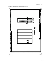
Страница 151: ...Dimensions 151 Location of input terminals ACS880 07XT 0810A 7 ACS880 07XT 0960A 7 ACS880 07XT 1010A 3 ACS880 07XT 1010A 5 ACS880 07XT 1190A 3 ACS880 07XT 1160A 5 ACS880 07XT 1080A 7 ...

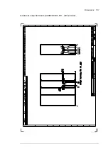
Страница 152: ...152 Dimensions Location of input terminals ACS880 07XT 1310A 5 ACS880 07XT 1320A 7 ACS880 07XT 1330A 3 ACS880 07XT 1610A 3 ACS880 07XT 1610A 5 ...

Страница 153: ...Dimensions 153 Location of input terminals ACS880 07XT 12 pulse ...

Страница 154: ...154 Dimensions Location of output terminals ACS880 07XT R10 with du dt ...

Страница 155: ...Dimensions 155 Location of output terminals ACS880 07XT R10 without du dt ...

Страница 156: ...156 Dimensions Location of output terminals ACS880 07XT R11 with du dt ...

Страница 157: ...Dimensions 157 Location of output terminals ACS880 07XT R11 without du dt ...

Страница 158: ...158 Dimensions Location of PE terminals ACS880 07XT ...

Страница 159: ...Dimensions 159 Location of resistor terminals ACS880 07XT R10 ...

Страница 160: ...160 Dimensions Location of resistor terminals ACS880 07XT R11 ...

Страница 161: ...age until the resistor can be disconnected Planning the braking system Selecting the default brake circuit components 1 Calculate the maximum power generated by the motor during braking Pmax 2 Select a suitable drive brake chopper and brake resistor combination for the application from the rating table The braking power of the chopper must be greater or equal than the maximum power generated by th...

Страница 162: ...g shielded cable or a metallic enclosure Unshielded single core cable can only be used if it is routed inside a cabinet that efficiently suppresses the radiated emissions Install the cables away from other cable routes Avoid long parallel runs with other cables The minimum parallel cabling separation distance should be 0 3 meters Cross the other cables at right angles Keep the cable as short as po...

Страница 163: ...peratures Protect the resistor against contact Protecting the system against thermal overload The brake chopper protects itself and the resistor cables against thermal overload when the cables are dimensioned according to the nominal current of the drive The drive control program includes a resistor and resistor cable thermal protection function which can be tuned by the user See the firmware manu...

Страница 164: ...y parameter 30 30 Overvoltage control Set parameter 31 01 External event 1 source to point to the digital input where the thermal switch of the brake resistor is wired Set parameter 31 02 External event 1 type to Fault Enable the brake chopper by parameter 43 06 Brake chopper enable If Enabled with thermal model is selected set also the brake resistor overload protection parameters 43 08 and 43 09...

Страница 165: ...le unit type ACS880 07XT Basic module type ACS8880 04 Internal brake chopper per basic brake module Example brake resistor s per basic module Pbrcont Rmin Type R ER PRcont kW ohm ohm kJ kW UN 400 V 1010A 3 585A 3 P943 315 1 3 2xSAFUR200F500 1 35 10800 27 1190A 3 650A 3 P943 315 1 3 2xSAFUR200F500 1 35 10800 27 1330A 3 725A 3 P943 400 0 7 3xSAFUR200F500 0 90 16200 40 1610A 3 880A 3 P943 400 0 7 3xS...

Страница 166: ... cable lead through data See section Terminal and lead through data for the power cables Brake resistor type ABB ordering code SAFUR125F500 68759285 SAFUR200F500 68759340 234 300 1320 Ø 7 345 1270 Brake resistor type Weight SAFUR125F500 25 kg 55 lb SAFUR200F500 30 kg 66 lb ...

Страница 167: ...ntacts can be found by navigating to www abb com searchchannels Product training For information on ABB product training navigate to new abb com service training Providing feedback on ABB Drives manuals Your comments on our manuals are welcome Navigate to new abb com drives manuals feedback form Document library on the Internet You can find manuals and other product documents in PDF format on the ...

Страница 168: ...www abb com drives www abb com drivespartners 3ABD00043579 Rev C EN 2018 01 01 Contact us ...

Отзывы: