

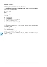


Use a double-shielded twisted pair cable for analog signals. This type of cable is
recommended for the pulse encoder signals also. Employ one individually shielded pair for
each signal. Do not use common return for different analog signals.
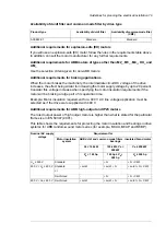
A double-shielded cable (figure a below) is the best alternative for low-voltage digital signals
but single-shielded (b) twisted pair cable is also acceptable.
a
b
■
Signals in separate cables
Run analog and digital signals in separate, shielded cables. Never mix 24 V DC and 115/230
V AC signals in the same cable.
■
Signals allowed to be run in the same cable
Relay-controlled signals, providing their voltage does not exceed 48 V, can be run in the
same cables as digital input signals. The relay-controlled signals should be run as twisted
pairs.
■
Relay cable type
The cable type with braided metallic screen (for example ÖLFLEX by LAPPKABEL, Germany)
has been tested and approved by ABB.
■
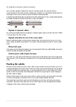
Control panel cable length and type
In remote use, the cable connecting the control panel to the drive must not be longer than
three meters (10 ft). Cable type: shielded CAT 5e or better Ethernet patch cable with RJ-45
ends.
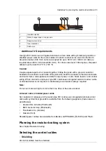
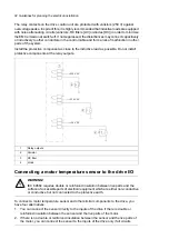
Routing the cables
Route the motor cable away from other cable routes. Cables of several motors can be run
in parallel installed next to each other. The motor cable, input power cable and control cables
should be installed on separate trays. Avoid long parallel runs of motor cables with other
cables in order to decrease electromagnetic interference caused by the rapid changes in
the drive output voltage.
Where control cables must cross power cables, make sure they are arranged at an angle
as near to 90 degrees as possible. Do not run extra cables through the drive.
The cable trays must have good electrical bonding to each other and to the grounding
electrodes. Aluminum tray systems can be used to improve local equalizing of potential.
A diagram of the cable routing is shown below.
86 Guidelines for planning the electrical installation
Содержание ACS880-07
Страница 1: ...ABB industrial drives Hardware manual ACS880 07 drives 560 to 2800 kW ...
Страница 2: ......
Страница 4: ......
Страница 22: ...22 ...
Страница 28: ...28 ...
Страница 94: ...94 ...
Страница 112: ...Electrical installation 109 5 6 4 3 112 Electrical installation ...
Страница 113: ...110 Electrical installation 7 8 8 Electrical installation 113 ...
Страница 114: ...Electrical installation 111 9 10 114 Electrical installation ...
Страница 116: ...Electrical installation 113 4 5 3 6 7 116 Electrical installation ...
Страница 118: ...2 11 b PE 10 7 5 6 8 a 360 grounding detail 118 Electrical installation ...
Страница 128: ...128 ...
Страница 146: ...146 ...
Страница 148: ...148 ...
Страница 159: ...12 Install and tighten the two M4 12 T20 screws 10 11 12 Maintenance 159 ...
Страница 162: ...6 6a 6a 6b 7a 7b 7 8 8a 8b 162 Maintenance ...
Страница 166: ...166 Maintenance 6 6 7 8 7 166 Maintenance ...
Страница 173: ...6 Reinstall the cover removed earlier and close the cubicle door 4 4 D7T D8T Maintenance 173 ...
Страница 213: ... Dimension drawing examples Frame 2 D7T 2 R8i 12 pulse A004 Dimensions 213 ...
Страница 214: ...Frame 1 D8T 2 R8i IP22 214 Dimensions ...
Страница 215: ...Frame 1 D8T 2 R8i IP54 B055 Dimensions 215 ...
Страница 216: ...Frame 1 D8T 2 R8i with common motor terminal cubicle H359 1 2 216 Dimensions ...
Страница 217: ...Frame 1 D8T 2 R8i with common motor terminal cubicle H359 2 2 Dimensions 217 ...
Страница 218: ...Frame 1 D8T 2 R8i with brake choppers and resistors D150 D151 1 2 218 Dimensions ...
Страница 219: ...Frame 1 D8T 2 R8i with brake choppers and resistors D150 D151 2 2 Dimensions 219 ...
Страница 220: ...Frame 1 D8T 2 R8i with sine output filter E206 1 2 220 Dimensions ...
Страница 221: ...Frame 1 D8T 2 R8i with sine output filter E206 2 2 Dimensions 221 ...
Страница 222: ...Frame 2 D8T 2 R8i 12 pulse A004 with grounding switch F259 222 Dimensions ...
Страница 223: ...Frame 2 D8T 3 R8i 1 2 Dimensions 223 ...
Страница 224: ...Frame 2 D8T 3 R8i 2 2 224 Dimensions ...
Страница 225: ...Frame 2 D8T 3 R8i with common motor terminal cubicle H359 1 2 Dimensions 225 ...
Страница 226: ...Frame 2 D8T 3 R8i with common motor terminal cubicle H359 2 2 226 Dimensions ...
Страница 227: ...Frame 2 D8T 3 R8i with top entry top exit H351 H353 1 2 Dimensions 227 ...
Страница 228: ...Frame 2 D8T 3 R8i with top entry top exit 2 2 228 Dimensions ...
Страница 229: ...Frame 3 D8T 4 R8i 1 2 Dimensions 229 ...
Страница 230: ...Frame 3 D8T 4 R8i 2 2 230 Dimensions ...
Страница 231: ...Frame 3 D8T 4 R8i with common motor terminal cubicle H359 1 2 Dimensions 231 ...
Страница 232: ...Frame 3 D8T 4 R8i with common motor terminal cubicle H359 2 2 232 Dimensions ...
Страница 233: ...Frame 3 D8T 4 R8i with top entry top exit H351 H353 1 2 Dimensions 233 ...
Страница 234: ...Frame 3 D8T 4 R8i with top entry top exit H351 H353 2 2 234 Dimensions ...
Страница 235: ...Frame 4 D8T 5 R8i 6 pulse with top entry exit UL Listed C129 1 2 Dimensions 235 ...
Страница 236: ...Frame 4 D8T 5 R8i 6 pulse with top entry exit UL Listed C129 2 2 236 Dimensions ...
Страница 237: ... Dimensions of empty cubicles options C199 C200 C201 IP22 IP42 Dimensions 237 ...
Страница 238: ...IP54 238 Dimensions ...
Страница 242: ... 600 mm with main breaker bottom cable entry 600 mm with main breaker top cable entry 242 Dimensions ...
Страница 243: ... 1000 mm UL CSA top cable entry Dimensions 243 ...
Страница 244: ... 1000 mm UL CSA bottom cable entry 244 Dimensions ...
Страница 264: ...264 ...
Страница 272: ... 272 ...
Страница 274: ...Contact us www abb com drives www abb com drivespartners 3AUA0000143261 E EN EFFECTIVE 2017 06 05 3AUA0000143261E ...


