


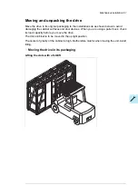


Miscellaneous
■
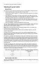
Cable duct in the floor below the cabinet
A cable duct can be constructed below the 500 mm wide middle part of the cabinet. The
cabinet weight lies on the two 50 mm wide transverse sections which the floor must carry.
Prevent the cooling air flow from the cable duct to the cabinet by bottom plates. To ensure
the degree of protection for the cabinet, use the original bottom plates delivered with the
unit. With user-defined cable entries, take care of the degree of protection, fire protection
and EMC compliance.
500 (19.68”)
50 (1.97”)
500
(
19.
68
”)
50 (1.97”)
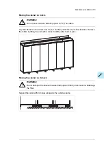
■
Arc welding
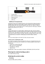
Fastening the cabinet by arc welding is not recommended. However, if arc welding is the
only mounting option, connect the return conductor of the welding equipment to the cabinet
frame at the bottom within 0.5 meters (1’6”) of the welding point.
Note:
The thickness of the zinc plating of the cabinet frame is 100 to 200 micrometers (4 to 8 mil).
WARNING!
Make sure that the return wire is connected correctly. Welding current must not
return via any component or cabling of the drive. If the welding return wire is
connected improperly, the welding circuit can damage electronic circuits in the
cabinet.
WARNING!
Do not inhale the welding fumes.
■
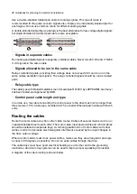
Air inlet through the bottom of cabinet (C128)
Drives with air intake through the bottom of the cabinet (C128) are intended for
installation on an air duct in the floor. Each cubicle (except top entry adapter and joining
cubicles) have an inlet through the bottom plate. The option also adds a 130 mm deep inlet
area at the back of the cubicle.
An example of the air inlets in the cabinet bottom plate is shown below. Refer also to the
dimension drawings delivered with the drive.
72 Mechanical installation
Содержание ACS880-07
Страница 1: ...ABB industrial drives Hardware manual ACS880 07 drives 560 to 2800 kW ...
Страница 2: ......
Страница 4: ......
Страница 22: ...22 ...
Страница 28: ...28 ...
Страница 94: ...94 ...
Страница 112: ...Electrical installation 109 5 6 4 3 112 Electrical installation ...
Страница 113: ...110 Electrical installation 7 8 8 Electrical installation 113 ...
Страница 114: ...Electrical installation 111 9 10 114 Electrical installation ...
Страница 116: ...Electrical installation 113 4 5 3 6 7 116 Electrical installation ...
Страница 118: ...2 11 b PE 10 7 5 6 8 a 360 grounding detail 118 Electrical installation ...
Страница 128: ...128 ...
Страница 146: ...146 ...
Страница 148: ...148 ...
Страница 159: ...12 Install and tighten the two M4 12 T20 screws 10 11 12 Maintenance 159 ...
Страница 162: ...6 6a 6a 6b 7a 7b 7 8 8a 8b 162 Maintenance ...
Страница 166: ...166 Maintenance 6 6 7 8 7 166 Maintenance ...
Страница 173: ...6 Reinstall the cover removed earlier and close the cubicle door 4 4 D7T D8T Maintenance 173 ...
Страница 213: ... Dimension drawing examples Frame 2 D7T 2 R8i 12 pulse A004 Dimensions 213 ...
Страница 214: ...Frame 1 D8T 2 R8i IP22 214 Dimensions ...
Страница 215: ...Frame 1 D8T 2 R8i IP54 B055 Dimensions 215 ...
Страница 216: ...Frame 1 D8T 2 R8i with common motor terminal cubicle H359 1 2 216 Dimensions ...
Страница 217: ...Frame 1 D8T 2 R8i with common motor terminal cubicle H359 2 2 Dimensions 217 ...
Страница 218: ...Frame 1 D8T 2 R8i with brake choppers and resistors D150 D151 1 2 218 Dimensions ...
Страница 219: ...Frame 1 D8T 2 R8i with brake choppers and resistors D150 D151 2 2 Dimensions 219 ...
Страница 220: ...Frame 1 D8T 2 R8i with sine output filter E206 1 2 220 Dimensions ...
Страница 221: ...Frame 1 D8T 2 R8i with sine output filter E206 2 2 Dimensions 221 ...
Страница 222: ...Frame 2 D8T 2 R8i 12 pulse A004 with grounding switch F259 222 Dimensions ...
Страница 223: ...Frame 2 D8T 3 R8i 1 2 Dimensions 223 ...
Страница 224: ...Frame 2 D8T 3 R8i 2 2 224 Dimensions ...
Страница 225: ...Frame 2 D8T 3 R8i with common motor terminal cubicle H359 1 2 Dimensions 225 ...
Страница 226: ...Frame 2 D8T 3 R8i with common motor terminal cubicle H359 2 2 226 Dimensions ...
Страница 227: ...Frame 2 D8T 3 R8i with top entry top exit H351 H353 1 2 Dimensions 227 ...
Страница 228: ...Frame 2 D8T 3 R8i with top entry top exit 2 2 228 Dimensions ...
Страница 229: ...Frame 3 D8T 4 R8i 1 2 Dimensions 229 ...
Страница 230: ...Frame 3 D8T 4 R8i 2 2 230 Dimensions ...
Страница 231: ...Frame 3 D8T 4 R8i with common motor terminal cubicle H359 1 2 Dimensions 231 ...
Страница 232: ...Frame 3 D8T 4 R8i with common motor terminal cubicle H359 2 2 232 Dimensions ...
Страница 233: ...Frame 3 D8T 4 R8i with top entry top exit H351 H353 1 2 Dimensions 233 ...
Страница 234: ...Frame 3 D8T 4 R8i with top entry top exit H351 H353 2 2 234 Dimensions ...
Страница 235: ...Frame 4 D8T 5 R8i 6 pulse with top entry exit UL Listed C129 1 2 Dimensions 235 ...
Страница 236: ...Frame 4 D8T 5 R8i 6 pulse with top entry exit UL Listed C129 2 2 236 Dimensions ...
Страница 237: ... Dimensions of empty cubicles options C199 C200 C201 IP22 IP42 Dimensions 237 ...
Страница 238: ...IP54 238 Dimensions ...
Страница 242: ... 600 mm with main breaker bottom cable entry 600 mm with main breaker top cable entry 242 Dimensions ...
Страница 243: ... 1000 mm UL CSA top cable entry Dimensions 243 ...
Страница 244: ... 1000 mm UL CSA bottom cable entry 244 Dimensions ...
Страница 264: ...264 ...
Страница 272: ... 272 ...
Страница 274: ...Contact us www abb com drives www abb com drivespartners 3AUA0000143261 E EN EFFECTIVE 2017 06 05 3AUA0000143261E ...


