


3)
0 = Acceleration/deceleration ramps defined by parameters 23.12/23.13 in use. 1 =
Acceleration/deceleration ramps defined by parameters 23.14/23.15 in use.
4)
Constant speed 1 is defined by parameter 22.26.
5)
See section
6)
Total load capacity of these outputs is 4.8 W (200 mA at 24 V) minus the power taken by
DIO1 and DIO2.
7)
Determines whether DICOM is separated from DIOGND (ie. common reference for digital
inputs floats; in practice, selects whether the digital inputs are used in current sinking or
sourcing mode). See also
Ground isolation diagram (page 139)
. DICOM=DIOGND ON:
DICOM connected to DIOGND. OFF: DICOM and DIOGND separate.
8)
Current [0(4)…20 mA,
R
in
= 100 ohm] or voltage [0(2)…10 V,
R
in
> 200 kohm] input
selected by switch AI1. Change of setting requires reboot of control unit.
9)
Current [0(4)…20 mA,
R
in
= 100 ohm] or voltage [0(2)…10 V,
R
in
> 200 kohm] input
selected by switch AI2. Change of setting requires reboot of control unit.
■
External power supply for the control unit (XPOW)
The BCU-x2 is powered from a 24 V DC, 2 A supply through terminal block XPOW. A second
supply can be connected to the same terminal block for redundancy.
■
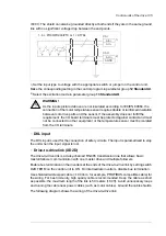
DI6 as a PTC sensor input
A PTC sensor can be connected to this input for motor temperature measurement as follows.
The sensor can alternatively be connected to FEN-xx encoder interface module. At the
sensor end of the cable, leave the shields unconnected or ground them indirectly via a
high-frequency capacitor with a few nanofarads, eg. 3.3 nF / 630 V. The shield can also be
grounded directly at both ends if they are in the same ground line with no significant voltage
drop between the end points. See the firmware manual for parameter settings.
T
3.3 nF
> 630 V AC
PTC
DI6
+24VD
WARNING!
As the inputs pictured above are not insulated according to IEC 60664, the
connection of the motor temperature sensor requires double or reinforced insulation
between motor live parts and the sensor. If the assembly does not fulfill the
requirement, the I/O board terminals must be protected against contact and must
not be connected to other equipment or the temperature sensor must be isolated
from the I/O terminals.
■
AI1 or AI2 as a Pt100, Pt1000, PTC or KTY84 sensor input
Three Pt100/Pt1000 sensors or one KTY84 sensor for motor temperature measurement
can be connected between an analog input and output as shown below. (Alternatively, you
can connect the KTY to an FIO-11 or FAIO-01 analog I/O extension module or FEN-xx
encoder interface module.) At the sensor end of the cable, leave the shields unconnected
or ground them indirectly via a high-frequency capacitor with a few nanofarads, eg. 3.3 nF
134 Control units of the drive
Содержание ACS880-07
Страница 1: ...ABB industrial drives Hardware manual ACS880 07 drives 560 to 2800 kW ...
Страница 2: ......
Страница 4: ......
Страница 22: ...22 ...
Страница 28: ...28 ...
Страница 94: ...94 ...
Страница 112: ...Electrical installation 109 5 6 4 3 112 Electrical installation ...
Страница 113: ...110 Electrical installation 7 8 8 Electrical installation 113 ...
Страница 114: ...Electrical installation 111 9 10 114 Electrical installation ...
Страница 116: ...Electrical installation 113 4 5 3 6 7 116 Electrical installation ...
Страница 118: ...2 11 b PE 10 7 5 6 8 a 360 grounding detail 118 Electrical installation ...
Страница 128: ...128 ...
Страница 146: ...146 ...
Страница 148: ...148 ...
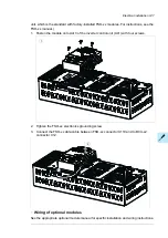
Страница 159: ...12 Install and tighten the two M4 12 T20 screws 10 11 12 Maintenance 159 ...
Страница 162: ...6 6a 6a 6b 7a 7b 7 8 8a 8b 162 Maintenance ...
Страница 166: ...166 Maintenance 6 6 7 8 7 166 Maintenance ...
Страница 173: ...6 Reinstall the cover removed earlier and close the cubicle door 4 4 D7T D8T Maintenance 173 ...
Страница 213: ... Dimension drawing examples Frame 2 D7T 2 R8i 12 pulse A004 Dimensions 213 ...
Страница 214: ...Frame 1 D8T 2 R8i IP22 214 Dimensions ...
Страница 215: ...Frame 1 D8T 2 R8i IP54 B055 Dimensions 215 ...
Страница 216: ...Frame 1 D8T 2 R8i with common motor terminal cubicle H359 1 2 216 Dimensions ...
Страница 217: ...Frame 1 D8T 2 R8i with common motor terminal cubicle H359 2 2 Dimensions 217 ...
Страница 218: ...Frame 1 D8T 2 R8i with brake choppers and resistors D150 D151 1 2 218 Dimensions ...
Страница 219: ...Frame 1 D8T 2 R8i with brake choppers and resistors D150 D151 2 2 Dimensions 219 ...
Страница 220: ...Frame 1 D8T 2 R8i with sine output filter E206 1 2 220 Dimensions ...
Страница 221: ...Frame 1 D8T 2 R8i with sine output filter E206 2 2 Dimensions 221 ...
Страница 222: ...Frame 2 D8T 2 R8i 12 pulse A004 with grounding switch F259 222 Dimensions ...
Страница 223: ...Frame 2 D8T 3 R8i 1 2 Dimensions 223 ...
Страница 224: ...Frame 2 D8T 3 R8i 2 2 224 Dimensions ...
Страница 225: ...Frame 2 D8T 3 R8i with common motor terminal cubicle H359 1 2 Dimensions 225 ...
Страница 226: ...Frame 2 D8T 3 R8i with common motor terminal cubicle H359 2 2 226 Dimensions ...
Страница 227: ...Frame 2 D8T 3 R8i with top entry top exit H351 H353 1 2 Dimensions 227 ...
Страница 228: ...Frame 2 D8T 3 R8i with top entry top exit 2 2 228 Dimensions ...
Страница 229: ...Frame 3 D8T 4 R8i 1 2 Dimensions 229 ...
Страница 230: ...Frame 3 D8T 4 R8i 2 2 230 Dimensions ...
Страница 231: ...Frame 3 D8T 4 R8i with common motor terminal cubicle H359 1 2 Dimensions 231 ...
Страница 232: ...Frame 3 D8T 4 R8i with common motor terminal cubicle H359 2 2 232 Dimensions ...
Страница 233: ...Frame 3 D8T 4 R8i with top entry top exit H351 H353 1 2 Dimensions 233 ...
Страница 234: ...Frame 3 D8T 4 R8i with top entry top exit H351 H353 2 2 234 Dimensions ...
Страница 235: ...Frame 4 D8T 5 R8i 6 pulse with top entry exit UL Listed C129 1 2 Dimensions 235 ...
Страница 236: ...Frame 4 D8T 5 R8i 6 pulse with top entry exit UL Listed C129 2 2 236 Dimensions ...
Страница 237: ... Dimensions of empty cubicles options C199 C200 C201 IP22 IP42 Dimensions 237 ...
Страница 238: ...IP54 238 Dimensions ...
Страница 242: ... 600 mm with main breaker bottom cable entry 600 mm with main breaker top cable entry 242 Dimensions ...
Страница 243: ... 1000 mm UL CSA top cable entry Dimensions 243 ...
Страница 244: ... 1000 mm UL CSA bottom cable entry 244 Dimensions ...
Страница 264: ...264 ...
Страница 272: ... 272 ...
Страница 274: ...Contact us www abb com drives www abb com drivespartners 3AUA0000143261 E EN EFFECTIVE 2017 06 05 3AUA0000143261E ...


