


■
Connections to the control unit
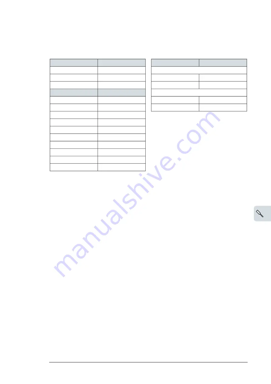
Connect the fiber optic, power supply and BGDR cables to the control unit as follows:
BCU control unit
ZINT/SOIA
BCU control unit
BPOW
Drive module 1
XPOW:1 (+24VI)
X3:1
V1T
ZINT: V1; SOIA: V10
XPOW:2 (GND)
X3:2
V1R
ZINT: V2; SOIA: V20
-
X3:3 (not used)
Drive module 2
BCU control unit
BGDR
V2T
ZINT: V1; SOIA: V10
(connector XSTO OUT)
Drive module 1
V2R
ZINT: V2; SOIA: V20
5 (IN1)
X7:1
6 (SGND)
X7:2
7 (IN2)
X8:1
8 (SGND)
X8:2
(connector XSTO OUT)
drive module 2
5 (IN1)
X7:1
6 (SGND)
X7:2
7 (IN2)
X8:1
8 (SGND)
X8:2
Connecting the control cables to the terminals of the
control unit
■
Control cable connection procedure
1.
Route the cables to the control unit.
2.
Strip the cable ends and conductors. When connecting to the drive I/O, use electrical
tape or shrink tubing to contain the strands. Elsewhere, twist the outer shield strands
into a bundle, crimp a lug onto it and connect it to the nearest chassis grounding point.
3.
Connect the conductors to the appropriate detachable terminals of the control unit, see
section
Default I/O connection diagram (page 110)
Note:
Keep any signal wire pairs twisted as close to the terminals as possible. Twisting the
wire with its return wire reduces disturbances caused by inductive coupling. Keep the shields
continuous as close to the terminals of the control unit as possible. Leave the other end of
the shield unconnected or ground it indirectly via a few nanofarads high-frequency capacitor,
eg, 3.3 nF / 630 V. The shield can also be grounded directly at both ends if they are in the
same ground line with no significant voltage drop between the end points.
Wiring the microswitches of the fuses
Wire the microswitches of the drive input fuses to the DIIL input as shown below or to an
external switch for stopping the drive in case of a blown fuse.
Electrical installation 99
11
Содержание ACS880-04FXT
Страница 1: ... ABB INDUSTRIAL DRIVES ACS880 04FXT drive module packages Hardware manual ...
Страница 2: ......
Страница 4: ......
Страница 40: ...40 ...
Страница 54: ...54 ...
Страница 82: ...82 ...
Страница 86: ...M10 86 Electrical installation ...
Страница 106: ...106 ...
Страница 114: ...FSO xx safety functions module connection X12 See the user manual of the FSO xx module 114 Control unit of the drive ...
Страница 118: ...118 ...
Страница 122: ...122 ...
Страница 132: ...132 ...
Страница 136: ...136 ...
Страница 158: ...158 ...
Страница 160: ...Standard configuration IP00 UL Type Open 160 Dimension drawings ...
Страница 161: ...Drive module with optional support brackets IP00 UL Type Open Dimension drawings 161 ...
Страница 162: ...Drive module with optional full size input and output power cable terminals and IP20 shrouds 162 Dimension drawings ...
Страница 163: ...Mounting plate opening 3AXD50000038119 Dimension drawings 163 ...
Страница 164: ...3AXD50000038119 164 Dimension drawings ...
Страница 182: ... Declaration of conformity 182 The Safe torque off function ...
Страница 183: ...The Safe torque off function 183 ...
Страница 184: ...184 ...


