


■
Connection procedure
•
Connect the resistor cables to the R+ and R- terminals in the same way as the other
power cables. If a shielded three-conductor cable is used, cut the third conductor and
ground the twisted shield of the cable (protective earth conductor of the resistor
assembly) at both ends.
•
Connect resistor cables to the R+ and R- terminals of both drive modules in the same
way as the other power cables. If a shielded three-conductor cable is used, cut the third
conductor and ground the twisted shield of the cable (protective earth conductor of the
resistor assembly) at both ends.
Note:
It is not possible to use only one brake chopper in the drive module package,
brake resistors must be connected to both drive modules.
•
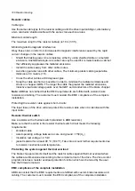
Wire the thermal switch to a digital input on the drive control unit as shown below.
Θ
+24VD
x
DIx
x
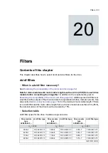
Start-up
Note:
New brake resistors may be coated with storage grease. As the brake chopper
operates for the first time, the grease burns off and may produce some smoke. Make sure
there is sufficient ventilation.
■
Parameter settings
Set the following parameters:
•
Disable the overvoltage control of the drive with parameter 30.30 Overvoltage control.
•
If the thermal switch is wired to the DIIL input, an overheating resistor will, by default,
remove the Run enable signal from the drive. See also parameters 20.11 Run enabe
stop mode, 20.12 Run enable 1 source and 95.20 HW options word 1.
•
If the thermal switch is wired to another digital input input, set the following parameters.
1.
Set the source of parameter 31.01 External event 1 source to point to the digital
input where the thermal switch of the brake resistor is wired.
2.
Enable the brake chopper by parameter 43.06 Brake chopper enable. If Enabled
with thermal model is selected, set also the brake resistor overload protection
parameters 43.08 and 43.09 according to the application.
3.
Set parameter 31.02 External event 1 type to Fault.
4.
Set parameter 43.07 Brake chopper run enable to Other [bit] and select from
parameter 10.01 DI status the digital input where the thermal switch of the brake
resistor is wired.
5.
Set the resistance value of the resistor to parameter 43.10 Brake resistance.
With these parameter settings, the drive generates a fault and coasts to a stop on brake
resistor overtemperature.
WARNING!
If the drive is equipped with a brake chopper but the chopper is not enabled by
the parameter setting, the internal thermal protection of the drive against resistor
overheating is not in use. In this case, the brake resistor must be disconnected.
190 Resistor braking
Содержание ACS880-04FXT
Страница 1: ... ABB INDUSTRIAL DRIVES ACS880 04FXT drive module packages Hardware manual ...
Страница 2: ......
Страница 4: ......
Страница 40: ...40 ...
Страница 54: ...54 ...
Страница 82: ...82 ...
Страница 86: ...M10 86 Electrical installation ...
Страница 106: ...106 ...
Страница 114: ...FSO xx safety functions module connection X12 See the user manual of the FSO xx module 114 Control unit of the drive ...
Страница 118: ...118 ...
Страница 122: ...122 ...
Страница 132: ...132 ...
Страница 136: ...136 ...
Страница 158: ...158 ...
Страница 160: ...Standard configuration IP00 UL Type Open 160 Dimension drawings ...
Страница 161: ...Drive module with optional support brackets IP00 UL Type Open Dimension drawings 161 ...
Страница 162: ...Drive module with optional full size input and output power cable terminals and IP20 shrouds 162 Dimension drawings ...
Страница 163: ...Mounting plate opening 3AXD50000038119 Dimension drawings 163 ...
Страница 164: ...3AXD50000038119 164 Dimension drawings ...
Страница 182: ... Declaration of conformity 182 The Safe torque off function ...
Страница 183: ...The Safe torque off function 183 ...
Страница 184: ...184 ...


