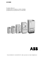
ABB ACS800-U4 Скачать руководство пользователя страница 1

ACS800

Hardware Manual
ACS800-04 Drive Modules (0.55 to 200 kW)
ACS800-U4 Drive Modules (0.75 to 200 HP)

Phone: 800.894.0412 - Fax: 888.723.4773 - Web: www.clrwtr.com - Email: [email protected]

Содержание ACS800-U4

Страница 1: ...ACS800 Hardware Manual ACS800 04 Drive Modules 0 55 to 200 kW ACS800 U4 Drive Modules 0 75 to 200 HP Phone 800 894 0412 Fax 888 723 4773 Web www clrwtr com Email info clrwtr com ...

Страница 2: ...Hardware Manual 55 to 2500 kW 75 to 2800 HP 3AFE68397260 English ACS800 37 Hardware Manual 55 to 2700 kW 75 to 3000 HP 3AFE68557925 English Safety instructions Electrical installation planning Mechanical and electrical installation Motor control and I O board RMIO Maintenance Technical data Dimensional drawings Resistor braking FIRMWARE MANUALS SUPPLEMENTS AND GUIDES appropriate documents are incl...

Страница 3: ...s 0 55 to 200 kW ACS800 U4 Drive Modules 0 75 to 200 HP Hardware Manual 3AFE68372984 Rev E EN EFFECTIVE 31 03 2008 2008 ABB Oy All Rights Reserved Phone 800 894 0412 Fax 888 723 4773 Web www clrwtr com Email info clrwtr com ...

Страница 4: ...Phone 800 894 0412 Fax 888 723 4773 Web www clrwtr com Email info clrwtr com ...

Страница 5: ...ke hydraulic crawling drives are able to rotate the motor directly or through any mechanical connection like felt nip rope etc NEW page 21 Terms and abbreviations The following term has been added to the Terms and abbreviations table The notice concerns the following ACS800 04 Drive Modules 0 55 to 200 kW and ACS800 U4 Drive Modules 0 75 to 200 HP Hardware Manuals Code 3AUA0000068979 Rev B Valid f...

Страница 6: ... according to standards EN 61800 5 2 2007 EN ISO 13849 1 2008 IEC 61508 and EN 62061 2005 The function also corresponds to an uncontrolled stop in accordance with category 0 of EN 60204 1 and prevention of unexpected start up of EN 1037 The STO may be used where power removal is required to prevent an unexpected start The function disables the control voltage of the power semiconductors of the dri...

Страница 7: ...Update Notice 3 Phone 800 894 0412 Fax 888 723 4773 Web www clrwtr com Email info clrwtr com ...

Страница 8: ... number Note If you add or modify the wiring in the drive safety circuits ensure that the appropriate standards e g IEC 61800 5 1 EN 62061 EN ISO 13849 1 and 2 and the ABB guidelines are met After making the changes verify the operation of the safety function by testing it CHANGED pages 67 68 Connecting the control cables Terminals Frame sizes R2 to R4 X41 Terminal for optional Prevention of unexp...

Страница 9: ...board 2 and drive terminal block X41 Connect a cable between connector X1 of the ASTO board 3 and the 24 V source Fasten the cover of the ASTO unit back with screws Note Location of the X41 terminal block varies according to the drive frame size see page 67 Note Maximum cable length between ASTO terminal block X2 and drive terminal block is restricted to 3 m For technical data see section ASTO 11C...

Страница 10: ...e 3 in this Update Notice NEW page 84 Installation check list The following step has been added to the ELECTRICAL INSTALLATION procedure Modules with the Safe torque off option 967 only ASTO board The Safe torque off circuit is completed and the supply voltage for ASTO 11C board is 24 V 3AUA0000069101 Phone 800 894 0412 Fax 888 723 4773 Web www clrwtr com Email info clrwtr com ...

Страница 11: ... drawings AGPS and ASTO boards The dimensions of the AGPS and ASTO boards are the same Nominal input voltage 24 V DC Nominal input current 40 mA 20mA per channel X1 terminal sizes 4 x 2 5 mm2 Nominal output current 0 4 A X2 terminal block type JST B4P VH Ambient temperature 0 50 C Relative humidity Max 90 no condensation allowed Dimensions with enclosure 167 x 128 x 52 mm Height x Weight x Depth W...

Страница 12: ...Update Notice 8 Phone 800 894 0412 Fax 888 723 4773 Web www clrwtr com Email info clrwtr com ...

Страница 13: ...rious injury or death and or damage to the equipment They also tell you how to avoid the danger Notes draw attention to a particular condition or fact or give information on a subject The warning symbols are used as follows Dangerous voltage warning warns of high voltage which can cause physical injury and or damage to the equipment General warning warns about conditions other than those caused by...

Страница 14: ...upplied control circuits may cause dangerous voltages inside the drive even when the main power on the drive is switched off Do not make any insulation or voltage withstand tests on the drive or drive modules When reconnecting the motor cable always check that the phase order is correct Note The motor cable terminals on the drive are at a dangerously high voltage when the input power is on regardl...

Страница 15: ...multiple drive installation connect each drive separately to protective earth PE In first environment EU EMC Directive make a 360 high frequency grounding of the motor cable entry at the cabinet lead through Do not install a drive with EMC filter option E202 or E200 on an ungrounded power system or a high resistance grounded over 30 ohms power system Note Power cable shields are suitable for equip...

Страница 16: ...st inside the unit may cause damage or malfunctioning Ensure sufficient cooling Do not fasten the drive by riveting or welding WARNING Ignoring the following instructions can cause damage to the printed circuit boards The printed circuit boards contain components sensitive to electrostatic discharge Wear a grounding wrist band when handling the boards Do not touch the boards unnecessarily WARNING ...

Страница 17: ...ated these functions will reset the drive and resume operation after a fault Do not control the motor with the disconnecting device means instead use the control panel keys and or commands via the I O board of the drive The maximum allowed number of charging cycles of the DC capacitors i e power ups by applying power is five in ten minutes Note If an external source for start command is selected a...

Страница 18: ...ate the motor directly or through any mechanical connection like felt nip rope etc Ensure that there is no voltage on the drive power terminals Alternative 1 Disconnect the motor from the drive with a safety switch or by other means Measure that there is no voltage present on the drive input or output terminals U1 V1 W1 U2 V2 W2 UDC UDC Alternative 2 Measure that there is no voltage present on the...

Страница 19: ...is manual What this chapter contains 17 Compatibility 17 Intended audience 17 Categorization according to the frame size 17 Categorization according to the code 17 Contents 18 Installation and commissioning flowchart 19 Product and service inquiries 20 Product training 20 Providing feedback on ABB Drives manuals 20 Terms and abbreviations 21 ACS800 04 U4 What this chapter contains 23 Layout 23 Typ...

Страница 20: ...Flange mounting 38 Planning the electrical installation What this chapter contains 41 Motor selection and compatibility 41 Protecting the motor insulation and bearings 42 Requirements table 43 Permanent magnet synchronous motor 46 Supply connection 46 Disconnecting device means 46 EEA Europe 47 US 47 Main contactor 47 Fuses 47 Thermal overload and short circuit protection 47 Thermal overload prote...

Страница 21: ... assembly 59 Drive 59 Input cable 59 Motor and motor cable 59 IT ungrounded systems 60 Power cable connection 61 Connecting the power cables 61 Grounding the motor cable shield at the motor end 62 Frame sizes R2 to R4 63 Frame size R5 63 Frame size R6 Cable lug installation 16 to 70 mm2 6 to 2 0 AWG cables 64 Power cable protection 65 Frame size R5 65 Frame size R6 66 Warning sticker 66 Connecting...

Страница 22: ...puts 81 DDCS fibre optic link 81 24 V DC power input 81 Installation checklist Checklist 83 Maintenance What this chapter contains 85 Safety 85 Maintenance intervals 85 Heatsink 85 Fan 86 Fan replacement R2 R3 86 Fan replacement R4 87 Fan replacement R5 88 Fan replacement R6 89 Additional fan 89 Replacement R2 R3 89 Replacement R4 R5 90 Replacement R6 90 Capacitors 90 Reforming 90 LEDs 90 Technica...

Страница 23: ...8 Degrees of protection 108 AGPS 11C 109 Ambient conditions 109 Materials 110 Applicable standards 110 CE marking 111 Definitions 111 Compliance with the EMC Directive 111 Compliance with the EN 61800 3 2004 111 First environment drive of category C2 111 Second environment drive of category C3 112 Second environment drive of category C4 112 Machinery Directive 112 C tick marking 113 Definitions 11...

Страница 24: ...kit for frame size R3 125 Flange mounting kit for frame size R4 126 Flange mounting kit for frame size R5 127 Flange mounting kit for frame size R6 128 AGPS board 129 Resistor braking What this chapter contains 131 Availability of brake choppers and resistors 131 How to select the correct drive chopper resistor combination 131 Optional brake chopper and resistor s 132 Resistor installation and wir...

Страница 25: ...e shown Special US instructions for installations within the United States that must be installed per the National Electrical Code and local codes are marked with US Categorization according to the frame size Some instructions technical data and dimensional drawings which concern only certain frame sizes are marked with the symbol of the frame size R2 R3 or R6 The frame size is not marked on the d...

Страница 26: ... the motor and cable selection the protections and the cable routing Electrical installation shows how to wire the drive Motor control and I O board RMIO shows the external control connections to the I O board Installation checklist contains a list for checking the mechanical and electrical installation of the drive Maintenance contains preventive maintenance instructions Technical data contains t...

Страница 27: ...chanical installation Unpacking the unit If the converter has been non operational for more than one year the converter DC link capacitors need to be reformed Ask ABB for instructions Check the installation site Mechanical installation Before installation Technical data If the drive is about to be connected to an IT ungrounded system check that the drive is not equipped with EMC filtering ACS800 0...

Страница 28: ... ABB Drives manuals Your comments on our manuals are welcome Go to ABB website then select successively Drives Document Library Manuals feedback form on the right pane Connect the power cables Connect the control and the auxiliary control cables Electrical installation Motor control and I O board RMIO Resistor braking optional and the optional module manual delivered with the module Check the inst...

Страница 29: ...ze of a drive module refer to the rating tables in chapter Technical data IGBT Insulated Gate Bipolar Transistor a voltage controlled semiconductor type widely used in inverters due to their easy controllability and high switching frequency I O Input Output AGPS Gate driver Power Supply board An optional board used to implement the Prevention of Unexpected Start function RDCO DDCS communication op...

Страница 30: ...About this manual 22 Phone 800 894 0412 Fax 888 723 4773 Web www clrwtr com Email info clrwtr com ...

Страница 31: ...ame sizes R2 to R6 is an IP20 drive module for controlling AC motors It is to be installed into a cabinet by the customer with wall fastening Control panel CDP312R Heatsink optional Frame size R2 Option slots PE Power cable terminal Location of the components vary depending on the frame size Phone 800 894 0412 Fax 888 723 4773 Web www clrwtr com Email info clrwtr com ...

Страница 32: ...age range nominal rating in bold 2 208 220 230 240 V AC 3 380 400 415 V AC 5 380 400 415 440 460 480 500 V AC 7 525 575 600 690 V AC options Control panel J400 Control panel CDP312R assembled on the drive module J414 Control panel holder for frame sizes R2 R3 and R4 not to be used with option J400 Construction C132 Marine drive coated boards included C135 Flange mounting Flange mounting plate asse...

Страница 33: ...BP RETA RRIA or RTAC Optional module 2 RTAC RAIO RRIA or RDIO DDCS communication option module 3 RDCO 01 RDCO 02 or RDCO 03 The fibre optic channels provided by the RDCO module can be used for fieldbus connection Nxxx fieldbus adapter modules PC connection DriveWare PC tools or Advant Fieldbus 100 connection e g AC 800M AC80 R UDC UDC R Brake chopper in frame sizes R2 R3 and 690 V frame R4 optiona...

Страница 34: ...based on the Direct Torque Control DTC method Two phase currents and DC link voltage are measured and used for the control The third phase current is measured for earth fault protection Component Description Six pulse rectifier Converts the three phase AC voltage to DC voltage Capacitor bank Energy storage which stabilizes the intermediate circuit DC voltage IGBT inverter Converts the DC voltage t...

Страница 35: ... sturdy enough to carry the weight of the drive components control circuitry and other equipment installed in it The cabinet must protect the drive module against contact and meet the requirements for dust and humidity see chapter Technical data Disposition of the devices For easy installation and maintenance a spacious layout is recommended Sufficient cooling air flow obligatory clearances cables...

Страница 36: ...le cooling air flow service and maintenance is shown below in millimetres and inches The temperature of the cooling air entering the unit must not exceed the maximum allowed ambient temperature See section Ambient conditions in chapter Technical data 200 7 9 300 12 IP20 UL open type Phone 800 894 0412 Fax 888 723 4773 Web www clrwtr com Email info clrwtr com ...

Страница 37: ...e roof Arrange the cooling air flow through the modules so that the requirements given in chapter Technical data are met cooling air flow Note The values in Technical data apply to continuous nominal load If the load is cyclic or less than nominal less cooling air is required allowed ambient temperature the air inlet and outlet sizes required for the module cooling and recommended filter material ...

Страница 38: ...y from the area where the inlet air to the cabinet is taken Possible solutions are listed below gratings that guide air flow at the air inlet and outlet air inlet and outlet at different sides of the cabinet cool air inlet in the lower part of the front door and an extra exhaust fan on the roof of the cabinet HOT AREA Main air flow out Main air flow in COOL AREA Cabinet side view HOT AREA Air flow...

Страница 39: ...area at the front part of the cabinet from the hot area back part The mounting plate can be fastened to two vertical pillars on both left and right Since the air outlet at the top of the modules points directly upwards the air must be guided to the hot area See cabinet layout examples below Cabinet layout example AC switch fuse AC fuses du dt filter Motor cable entries Airflow guides AC fuse bases...

Страница 40: ...ened directly to the cabinet door or to a mounting platform Installing the control panel directly on the cabinet door Fasten the control panel from the back side with two screws of one of the following types standard screw with nominal diameter of 4 mm 0 16 in tapping screw with nominal diameter of 4 2 mm 0 17 in DIN 7981 C DIN 7982 C DIN 7983 C or DIN 7976 C PT screw for thermoplastics with nomin...

Страница 41: ... silicon mass covered with a metal mesh The non tightened touch contact of the metal surfaces is not sufficient so a conductive gasket between the surfaces is required The maximum recommended distance between assembly screws is 100 mm Sufficient high frequency grounding network must be constructed in the cabinet to avoid voltage differences and forming of high impedance radiator structures A good ...

Страница 42: ... at their entries The shields can be grounded by means of conductive shielding cushions pressed against the cable shield from both directions Shielding cushion conductive Cable Cable grommet Bare cable shield Cabinet bottom plate Phone 800 894 0412 Fax 888 723 4773 Web www clrwtr com Email info clrwtr com ...

Страница 43: ...ic bag containing screws M3 clamps and cable lugs 2 mm2 M3 for grounding the control cable screens residual voltage warning stickers hardware firmware and other module manuals delivery documents Unpack the unit of frame sizes R2 to R5 as follows Tear Phone 800 894 0412 Fax 888 723 4773 Web www clrwtr com Email info clrwtr com ...

Страница 44: ...nufacturing year and week respectively The remaining digits complete the serial number so that there are no two units with the same serial number The type designation label is attached to the heat sink and the serial number label to the upper part of the back plate of the unit Before installation Check the installation site according to the requirements below See Dimensional drawings for frame det...

Страница 45: ...e sizes R2 R5 use the mounting template cut from the package 2 Fix the screws or bolts to the marked locations 3 Position the drive onto the screws on the cabinet wall Note Lift the drive by its chassis R6 by its lifting holes 4 Tighten the screws in the cabinet wall securely 1 Phone 800 894 0412 Fax 888 723 4773 Web www clrwtr com Email info clrwtr com ...

Страница 46: ...losed M6 rivet nut L 23 mm code 23351060030 Rivkle provided by Böllhoff www boellhoff de 2 Lift the drive by its lifting lugs and place it into the mounting hole 3 Fix the washers and screws M6 delivered with the drive MRP code 68390419 The tightening torque is 2 Nm Note The flange mounting kit does not ground the drive The drive needs to be grounded according to instructions given in chapter Elec...

Страница 47: ...Mechanical installation 39 1 2 Washer Screw 3 Lifting lug R6 flange mounting Mounting plate Phone 800 894 0412 Fax 888 723 4773 Web www clrwtr com Email info clrwtr com ...

Страница 48: ...Mechanical installation 40 Phone 800 894 0412 Fax 888 723 4773 Web www clrwtr com Email info clrwtr com ...

Страница 49: ...applicable 2 Check that the motor ratings lie within the allowed ranges of the drive control program motor nominal voltage is 1 2 2 UN of the drive motor nominal current is 1 6 2 I2hd of the drive in DTC control and 0 2 I2hd in scalar control The control mode is selected by a drive parameter 3 Check that the motor voltage rating meets the application requirements If no resistor braking is in use t...

Страница 50: ...on the attenuation and reflection properties of the motor cable and the terminals This in turn can cause additional stress on the motor and motor cable insulation Modern variable speed drives with their fast rising voltage pulses and high switching frequencies can generate current pulses that flow through the motor bearings which can gradually erode the bearing races and rolling elements The stres...

Страница 51: ...em ABB du dt filter insulated N end bearing and ABB common mode filter PN 100 kW and frame size IEC 315 100 kW PN 350 kW or frame size IEC 315 PN 350 kW or frame size IEC 400 PN 134 HP and frame size NEMA 500 134 HP PN 469 HP or frame size NEMA 500 PN 469 HP or frame size NEMA 580 A B B Random wound M2_ and M3_ UN 500 V Standard N N CMF 500 V UN 600 V Standard du dt du dt N du dt N CMF or Reinforc...

Страница 52: ...dt N du dt N CMF or du dt CMF or Reinforced ÛLL 1600 V 0 2 microsecond rise time N or CMF N CMF 500 V UN 600 V Reinforced ÛLL 1600 V du dt du dt N du dt N CMF or du dt CMF or Reinforced ÛLL 1800 V N or CMF N CMF 600 V UN 690 V Reinforced ÛLL 1800 V du dt du dt N du dt N CMF Reinforced ÛLL 2000 V 0 3 microsecond rise time N CMF N CMF Manufacturer Motor type Nominal mains voltage AC line voltage Req...

Страница 53: ...the drive is in braking mode for a large part of its operation time the intermediate circuit DC voltage of the drive increases the effect being similar to increasing the supply voltage by up to 20 percent The voltage increase should be taken into consideration when determining the motor insulation requirement Example Motor insulation requirement for a 400 V application must be selected as if the d...

Страница 54: ...ilter is approximately 1 5 UN Note 9 Common mode filter is available as a separate kit one box including three rings for one cable Permanent magnet synchronous motor Only one permanent magnet motor can be connected to the inverter output It is recommended to install a safety switch between the permanent magnet synchronous motor and the drive output The switch is needed to isolate the motor during ...

Страница 55: ... Main contactor If used dimension the contactor according to the nominal voltage and current of the drive The utilization category IEC 947 4 is AC 1 Fuses See section Thermal overload and short circuit protection Thermal overload and short circuit protection Thermal overload protection of the drive and the input and motor cables The drive protects itself and the input and motor cables against ther...

Страница 56: ...formation on the motor thermal protection and the connection and use of the temperature sensors Protection against short circuit in the motor cable The drive protects the motor cable and motor in a short circuit situation when the motor cable is dimensioned according to the nominal current of the drive No additional protection devices are needed Protection against short circuit inside the drive or...

Страница 57: ...must not be used without fuses in the USA Ground fault protection The drive is equipped with an internal ground fault protective function to protect the unit against ground faults in the motor and the motor cable This is not a personal safety or a fire protection feature The ground fault protective function can be disabled with a parameter refer to the appropriate ACS800 Firmware Manual The EMC fi...

Страница 58: ...1 categories 1 and 3 when the following installations are made The user must install on a control desk near the machinery switching disconnecting device for the circuitry Means shall be provided to prevent inadvertent and or mistaken closure of the disconnecting device EN 60204 1 1997 indicating lamp on starting the drive is prevented off drive is operative safety relay type BD5935 has been approv...

Страница 59: ...R4 with up to 30 kW 40 HP motors but shielded symmetrical motor cable is always recommended The shield s of motor cable s must have 360 bonding at both ends Note When continuous metal conduit is employed shielded cable is not required The conduit must have bonding at both ends as with cable shield A four conductor system is allowed for input cabling but shielded symmetrical cable is recommended To...

Страница 60: ...ighter the shield the lower the emission level and the bearing currents Symmetrical shielded cable three phase conductors and a concentric or otherwise symmetrically constructed PE conductor and a shield Recommended PE conductor and shield Shield Shield A separate PE conductor is required if the conductivity of the cable shield is 50 of the conductivity of the phase conductor A four conductor syst...

Страница 61: ...ts also to the drive enclosure and motor frame Use separate conduits for input power motor brake resistor and control wiring When conduit is employed type MC continuous corrugated aluminium armor cable or shielded cable is not required A dedicated ground cable is always required Note Do not run motor wiring from more than one drive in the same conduit Armored cable shielded power cable Six conduct...

Страница 62: ...at the power factor compensation unit is suitable for use in systems with AC drives i e harmonic generating loads In such systems the compensation unit should typically be equipped with a blocking reactor or harmonic filter Equipment connected to the motor cable Installation of safety switches contactors connection boxes etc To minimize the emission level when safety switches contactors connection...

Страница 63: ...d off The relay contacts on the RMIO board are protected with varistors 250 V against overvoltage peaks In spite of this it is highly recommended to equip inductive loads with noise attenuating circuits varistors RC filters AC or diodes DC in order to minimize the EMC emission at switch off If not suppressed the disturbances may connect capacitively or inductively to other conductors in the contro...

Страница 64: ...ls in separate shielded cables Relay controlled signals providing their voltage does not exceed 48 V can be run in the same cables as digital input signals It is recommended that the relay controlled signals be run as twisted pairs Never mix 24 V DC and 115 230 V AC signals in the same cable Relay cable The cable type with braided metallic screen e g ÖLFLEX by LAPPKABEL Germany has been tested and...

Страница 65: ...0 Firmware Manual Installation sites above 2000 metres 6562 feet WARNING Protect against direct contact when installing operating and servicing the RMIO board wiring and optional modules attached to the board The Protective Extra Low Voltage PELV requirements stated in EN 50178 are not fulfilled at altitudes above 2000 m 6562 ft Routing the cables Route the motor cable away from other cable routes...

Страница 66: ...n 200 mm 8 in min 300 mm 12 in Motor cable Power cable Drive 24 V 24 V 230 V Lead 24 V and 230 V 120 V control cables in separate ducts inside the cabinet Not allowed unless the 24 V cable is insulated for 230 V 120 V or insulated with an insulation sleeving for 230 V 120 V 120 V 230 V 120 V Phone 800 894 0412 Fax 888 723 4773 Web www clrwtr com Email info clrwtr com ...

Страница 67: ...gger on any part of the drive as testing can damage the drive Every drive has been tested for insulation between the main circuit and the chassis 2500 V rms 50 Hz for 1 second at the factory Also there are voltage limiting circuits inside the drive which cut down the testing voltage automatically Input cable Check the insulation of the input cable according to local regulations before connecting i...

Страница 68: ...o an ungrounded system For detailed instructions on how to do this please contact your local ABB distributor WARNING If a drive with EMC filter selection E202 or E200 is installed on an IT system an ungrounded power system or a high resistance grounded over 30 ohms power system the system will be connected to earth potential through the EMC filter capacitors of the drive This may cause danger or d...

Страница 69: ...stallation Selecting the power cables 360 degrees grounding is required at the cabinet entry in first environment installations First environment EMC compliance is defined in chapter Technical data Note If there is a symmetrically constructed grounding conductor in the motor cable in addition to the conductive shield connect the grounding conductor to the grounding terminal at the drive and motor ...

Страница 70: ...t Secure the cables outside the unit mechanically Ground the other end of the input cable shield or PE conductor at the distribution board Grounding the motor cable shield at the motor end For minimum radio frequency interference ground the cable shield 360 degrees at the lead through of the motor terminal box or ground the cable by twisting the shield as follows flattened width 1 5 length Frame s...

Страница 71: ...izes R2 to R4 Frame size R5 Input power cable Motor cable U1 V1 W1 UDC R R UDC U2 V2 W2 PE PE U2 V2 W2 PE UDC R UDC R V1 U1 W1 PE Input power cable Motor cable Phone 800 894 0412 Fax 888 723 4773 Web www clrwtr com Email info clrwtr com ...

Страница 72: ... U1 U1 U1 V1 W1 U2 V2 W2 R UDC R UDC Input power cable Motor cable Isolate the ends of the cable lugs with insulating tape or shrink tube Remove the screw terminals Fasten the cable lugs to the remaining bolts with M10 nuts Phone 800 894 0412 Fax 888 723 4773 Web www clrwtr com Email info clrwtr com ...

Страница 73: ... 2 Press the shroud onto the terminals a b PE U1 U1 U1 V1 W1 U2 V2 W2 R UDC R UDC Input power cable Motor cable a Connect the cable to the terminal b Connect the terminal to the drive WARNING If the wire size is less than 95 mm2 3 0 AWG a cable lug must be used A cable of wire size less than 95 mm2 3 0 AWG connected to this terminal will loosen and may damage the drive 1 2 2 Phone 800 894 0412 Fax...

Страница 74: ...e shroud onto the terminals Removal of the shroud by lifting up with a screw driver from the corner Warning sticker There are warning stickers in different languages inside the packing box of the drive Attach a warning sticker in the language of your choice onto the plastic skeleton above the power cable terminals 2 1 View of cable terminal installation Phone 800 894 0412 Fax 888 723 4773 Web www ...

Страница 75: ...1 Optional module 2 Frame sizes R2 to R4 The control cable connection terminals are exposed when the control panel mounting platform is turned aside by pulling this knob Be careful do not use excess force when pulling control panel is an option X39 for control panel cable Place the warning sticker here DDCS communication option module 3 RDCO Relay outputs 1 2 3 4 X41 Terminal for optional Preventi...

Страница 76: ...lace the warning sticker here Control cable grounding see section 360 degrees grounding DDCS communication option module 3 RDCO View of frame size R6 X41 for Prevention of Unexpected Start AGPS board optional Terminal for optional Prevention of Unexpected Start X41 Phone 800 894 0412 Fax 888 723 4773 Web www clrwtr com Email info clrwtr com ...

Страница 77: ...th a cable lug and a screw Double shielded cables Connect each pair cable shield twisted grounding wires with other pair cable shields of the same cable to the nearest grounding hole with a cable lug and a screw Do not connect shields of different cables to the same cable lug and grounding screw Leave the other end of the shield unconnected or ground it indirectly via a few nanofarads high frequen...

Страница 78: ...stripped part of the cable under the clamp Be careful Do not cut the grounding wire Clamp as close to the terminals as possible As short as possible Note1 If the encoder is of unisolated type ground the encoder cable at the drive end only If the encoder is galvanically isolated from the motor shaft and the stator frame ground the encoder cable shield at the drive and the encoder end Note 2 Twist t...

Страница 79: ...supply for the RMIO board via terminal X34 For the current consumption of the RMIO board see chapter Motor control and I O board RMIO Note External power is easier to supply to the RMIO board via terminal X23 see chapter Motor control and I O board RMIO Parameter settings In Standard Control Program set parameter 16 09 CTRL BOARD SUPPLY to EXTERNAL 24V if the RMIO board is powered from an external...

Страница 80: ...Electrical installation 72 1 Frame sizes R2 to R4 Frame sizes R5 and R6 1 3 4 4 2 X34 Phone 800 894 0412 Fax 888 723 4773 Web www clrwtr com Email info clrwtr com ...

Страница 81: ...llation 73 5 6 7 8 1 2 RMIO board X34 1 2 3 RMIO board X34 Connection of a two way connector 1 2 3 1 2 3 Connection of a three way connector Phone 800 894 0412 Fax 888 723 4773 Web www clrwtr com Email info clrwtr com ...

Страница 82: ...lation and maintenance If the drive is already connected to the mains wait for 5 min after disconnecting mains power Connect the optional AGPS board as follows Remove the enclosure cover by undoing the fixing screws 1 Ground the unit via the bottom plate of the enclosure or via terminal X1 1 of the AGPS board Connect the cable delivered with the kit between terminal block X2 of the AGPS board 2 an...

Страница 83: ...g to the drive frame size see page 67 Note Maximum cable length between AGPS terminal block X2 and drive terminal block is restricted to 10 m For technical data see section AGPS 11C in chapter Technical data Phone 800 894 0412 Fax 888 723 4773 Web www clrwtr com Email info clrwtr com ...

Страница 84: ...ctrical installation 76 The following figure presents the circuit diagram of the Prevention of Unexpected Start 3AFE00374994 U4 Phone 800 894 0412 Fax 888 723 4773 Web www clrwtr com Email info clrwtr com ...

Страница 85: ...put power supply fieldbus communication is required when the input power supply is disconnected The RMIO board can be supplied from an external power source via terminal X23 or X34 or via both X23 and X34 The internal power supply to terminal X34 can be left connected when using terminal X23 WARNING If the RMIO board is supplied from an external power source via terminal X34 the loose end of the c...

Страница 86: ... 2 5 DI5 Constant speed select 3 6 DI6 Constant speed select 3 7 24VD 24 V DC max 100 mA 8 24VD 9 DGND1 Digital ground 10 DGND2 Digital ground 11 DIIL Start interlock 0 stop 4 X23 1 24V Auxiliary voltage output and input non isolated 24 V DC 250 mA 5 2 GND X25 1 RO1 Relay output 1 ready 2 RO1 3 RO1 X26 1 RO2 Relay output 2 running 2 RO2 3 RO2 X27 1 RO3 Relay output 3 fault 1 2 RO3 3 RO3 Fault A rp...

Страница 87: ... 5 DI5 Constant speed select 3 6 DI6 Constant speed select 3 7 24VD 24 V DC max 100 mA 8 24VD 9 DGND1 Digital ground 10 DGND2 Digital ground 11 DIIL Start interlock 0 stop 4 X23 1 24V Auxiliary voltage output and input non isolated 24 V DC 250 mA 5 2 GND X25 1 RO1 Relay output 1 ready 2 RO1 3 RO1 X26 1 RO2 Relay output 2 running 2 RO2 3 RO2 X27 1 RO3 Relay output 3 fault 1 2 RO3 3 RO3 Fault A rpm ...

Страница 88: ...hm Auxiliary power output Voltage 24 V DC 10 short circuit proof Maximum current 250 mA without any optional modules inserted onto slots 1 and 2 Analogue outputs Two programmable current outputs 0 4 to 20 mA RL 700 ohm Resolution 0 1 10 bit Inaccuracy 1 Full Scale Range at 25 C 77 F Temperature coefficient 200 ppm C 111 ppm F max Digital inputs With Standard Control Program six programmable digita...

Страница 89: ... Drives Communication System 24 V DC power input Voltage 24 V DC 10 Typical current consumption without optional modules 250 mA Maximum current consumption 1200 mA with optional modules inserted The terminals on the RMIO board as well as on the optional modules attachable to the board fulfil the Protective Extra Low Voltage PELV requirements stated in EN 50178 provided that the external circuits c...

Страница 90: ...0 DGND2 X23 1 24 V 2 GND X25 1 RO1 2 RO1 3 RO1 X26 1 RO2 2 RO2 3 RO2 X27 1 RO3 2 RO3 3 RO3 Common mode voltage between channels 15 V J1 Test voltage 500 V AC or Jumper J1 settings All digital inputs share a common ground This is the default setting Grounds of input groups DI1 DI4 and DI5 DI6 DIIL are separate insulation voltage 50 V Ground Test voltage 4 kV AC Phone 800 894 0412 Fax 888 723 4773 W...

Страница 91: ...the EMC filter option E202 E200 or the E202 and E200 EMC filter capacitors are disconnected if the drive is connected to an IT ungrounded system The capacitors are reformed if stored over one year refer to ACS600 800 Capacitor Reforming Guide 3AFE64059629 English The drive is grounded properly The mains input power voltage matches the drive nominal input voltage The mains input power connections a...

Страница 92: ...ecklist 84 Modules with prevention of unexpected start option only AGPS board The prevention of unexpected start circuit is completed Check Phone 800 894 0412 Fax 888 723 4773 Web www clrwtr com Email info clrwtr com ...

Страница 93: ...sink should be checked annually in a dusty environment more often Clean the heatsink as follows when necessary 1 Remove the cooling fan see section Fan 2 Blow clean compressed air not humid from bottom to top and simultaneously use a vacuum cleaner at the air outlet to trap the dust Note If there is a risk of the dust entering adjoining equipment perform the cleaning in another room 3 Replace the ...

Страница 94: ...can be predicted by the increasing noise from fan bearings and the gradual rise in the heatsink temperature in spite of heatsink cleaning If the drive is operated in a critical part of a process fan replacement is recommended once these symptoms start appearing Replacement fans are available from ABB Do not use other than ABB specified spare parts Fan replacement R2 R3 To remove the fan release th...

Страница 95: ...ounting plate to the left and pull it out 3 Disconnect the fan power cable 4 Undo the screws that fasten the fan to the fan mounting plate 5 Install the new fan in reverse order 3 1 1 2 Bottom view 4 4 4 4 View from above fan plate pulled out Phone 800 894 0412 Fax 888 723 4773 Web www clrwtr com Email info clrwtr com ...

Страница 96: ...crews of the swing out frame 2 Open the swing out frame 3 Disconnect the cable 4 Undo the fastening screws of the fan 5 Install the new fan in reverse order Bottom view 1 1 3 2 4 4 Phone 800 894 0412 Fax 888 723 4773 Web www clrwtr com Email info clrwtr com ...

Страница 97: ...ional fan in all types except in 0001 2 0002 2 0003 2 0003 3 0004 3 0005 3 0004 5 0005 5 and 0006 5 Replacement R2 R3 To remove the fan release the retaining clip 1 Disconnect the cable 2 detachable terminal Install the new fan in reverse order 1 2 Bottom view 1 1 2 View from above Air flow upwards Rotation direction Phone 800 894 0412 Fax 888 723 4773 Web www clrwtr com Email info clrwtr com ...

Страница 98: ...temperature Capacitor life can be prolonged by lowering the ambient temperature It is not possible to predict a capacitor failure Capacitor failure is usually followed by a mains fuse failure or a fault trip Contact ABB if capacitor failure is suspected Replacements for frame size R4 and up are available from ABB Do not use other than ABB specified spare parts Reforming Reform re age spare part ca...

Страница 99: ...pply voltage 208 V 220 V 230 V or 240 V 0001 2 5 1 6 5 1 1 4 7 0 75 3 4 0 55 R2 35 100 0002 2 6 5 8 2 1 5 6 0 1 1 4 3 0 75 R2 35 100 0003 2 8 5 10 8 1 5 7 7 1 5 5 7 1 1 R2 35 100 0004 2 10 9 13 8 2 2 10 2 2 2 7 5 1 5 R2 35 120 0005 2 13 9 17 6 3 12 7 3 9 3 2 2 R2 35 140 0006 2 19 24 4 18 4 14 3 R3 69 160 0009 2 25 32 5 5 24 5 5 19 4 R3 69 200 0011 2 34 46 7 5 31 7 5 23 5 5 R3 69 250 0016 2 44 62 1...

Страница 100: ... V 400 V 415 V 440 V 460 V 480 V or 500 V 0004 5 4 9 6 5 2 2 4 5 2 2 3 4 1 5 R2 35 120 0005 5 6 2 8 2 3 5 6 3 4 2 2 2 R2 35 140 0006 5 8 1 10 8 4 7 7 4 5 6 3 R2 35 160 0009 5 10 5 13 8 5 5 10 5 5 7 5 4 R2 35 200 0011 5 13 2 17 6 7 5 12 7 5 9 2 5 5 R2 35 250 0016 5 19 24 11 18 11 13 7 5 R3 69 340 0020 5 25 32 15 23 15 18 11 R3 69 440 0025 5 34 46 18 5 31 18 5 23 15 R3 69 530 0028 5 38 46 22 37 22 2...

Страница 101: ...60 7 57 84 55 52 45 42 37 R5 250 1010 0070 7 79 104 75 73 55 54 45 R6 405 1220 0100 7 93 124 90 86 75 62 55 R6 405 1650 0120 7 113 172 110 108 90 86 75 R6 405 1960 0145 7 134 190 132 125 110 95 90 R6 405 2660 0175 7 166 245 160 155 132 131 110 R6 405 3470 0205 7 190 245 160 180 160 147 132 R6 405 4180 PDM code 00096931 J Nominal ratings Icont max continuous rms output current No overload capabilit...

Страница 102: ... I2hd Altitude derating In altitudes from 1000 to 4000 m 3300 to 13123 ft above sea level the derating is 1 for every 100 m 328 ft For a more accurate derating use the DriveSize PC tool See Installation sites above 2000 metres 6562 feet on page 57 Cooling characteristics Cooling requirements for flange mounting ACS800 04 frame size Minimum effective area of air inlet Minimum effective area of air ...

Страница 103: ...size Three phase supply voltage 208 V 220 V 230 V or 240 V 0001 2 4 4 10 483 500 ABB Control OFAF000H10 000 0002 2 5 2 10 483 500 ABB Control OFAF000H10 000 0003 2 6 7 10 483 500 ABB Control OFAF000H10 000 0004 2 9 3 16 993 500 ABB Control OFAF000H16 000 0005 2 12 16 993 500 ABB Control OFAF000H16 000 0006 2 16 20 1620 500 ABB Control OFAF000H20 000 0009 2 23 25 3100 500 ABB Control OFAF000H25 000...

Страница 104: ... 483 500 ABB Control OFAF000H10 000 0009 5 10 0 16 993 500 ABB Control OFAF000H16 000 0011 5 12 5 16 993 500 ABB Control OFAF000H16 000 0016 5 17 20 1620 500 ABB Control OFAF000H20 000 0020 5 23 25 3100 500 ABB Control OFAF000H25 000 0025 5 31 40 9140 500 ABB Control OFAF000H40 000 0028 5 36 50 15400 500 ABB Control OFAF000H50 000 0030 5 41 50 15400 500 ABB Control OFAF000H50 000 0040 5 47 63 2130...

Страница 105: ...082 ohm km The calculated short circuit current 2 7 kA is higher than the minimum short circuit current of the drive gG fuse type OFAF00H160 2400 A The 500 V gG fuse ABB Control OFAF00H160 can be used 430 V 2 600 kVA 22 19 mohm Zk zk UN 2 SN 0 072 m 0 398 ohm km 67 66 mohm Rc 170 m 0 082 ohm km 13 94 mohm Xc 170 410 V 2 67 66 mohm 2 22 19 mohm 13 94 mohm 2 Ik2 ph 2 7 kA Phone 800 894 0412 Fax 888 ...

Страница 106: ...0 0070 3 138 2400 160 200000 500 ABB Control OFAF00H160 00 0100 3 163 2850 200 350000 500 ABB Control OFAF1H200 1 0120 3 198 3300 224 420000 500 ABB Control OFAF1H224 1 0135 3 221 3820 250 550000 500 ABB Control OFAF1H250 1 0165 3 254 4510 315 1100000 500 ABB Control OFAF2H315 2 0205 3 286 4510 315 1100000 500 ABB Control OFAF2H315 2 Three phase supply voltage 380 V 400 V 415 V 440 V 460 V 480 V o...

Страница 107: ... 0070 3 138 1630 315 80500 690 Bussmann 170M1572 DIN000 0100 3 163 1280 315 46500 690 Bussmann 170M3817 DIN1 0120 3 198 1810 400 105000 690 Bussmann 170M3819 DIN1 0135 3 221 2210 500 145000 690 Bussmann 170M5810 DIN2 0165 3 254 2620 550 190000 690 Bussmann 170M5811 DIN2 0205 3 286 2620 550 190000 690 Bussmann 170M5811 DIN2 Three phase supply voltage 380 V 400 V 415 V 440 V 460 V 480 V or 500 V 005...

Страница 108: ...99 99 140 0070 3 3 70 Cu 3 95 Al 130 140 170 100 100 140 0100 3 3 95 Cu 3 120 Al 160 170 200 120 120 140 0120 3 3 120 Cu 3 185 Al 180 190 220 150 150 150 0135 3 3 150 Cu 3 240 Al 210 220 260 160 160 160 0165 3 3 185 Cu 3 240 Al 250 270 320 190 190 200 0205 3 3 240 Cu 2 3 95 Al 232 257 310 134 153 196 Three phase supply voltage 380 V 400 V 415 V 440 V 460 V 480 V or 500 V 0050 5 3 25 Cu 3 35 Al 67 ...

Страница 109: ...me and lead to unnecessary operation of the fuses In case of any uncertainty regarding the drive protection please contact your local ABB Cable types The table below gives copper and aluminium cable types for different load currents Cable sizing is based on max 9 cables laid on a cable ladder side by side ambient temperature 30 C PVC insulation surface temperature 70 C EN 60204 1 and IEC 60364 5 5...

Страница 110: ...tions included in the drive Frame size U1 V1 W1 U2 V2 W2 R R Earthing PE Maximum wire size Tightening torque Maximum wire size Tightening torque mm2 Nm mm2 Nm R2 up to 16 1 2 1 5 up to 10 1 5 R3 up to 16 1 2 1 5 up to 10 1 5 R4 up to 25 2 4 up to 16 3 0 R5 6 70 15 6 70 15 R6 95 185 20 40 95 8 Frame size Height Width Depth Weight Noise mm mm mm kg dB R2 370 165 193 226 8 62 R3 420 173 231 5 265 13 ...

Страница 111: ...0 0040 2 138 104 40 80 30 R5 147 2770 0050 2 164 132 50 104 40 R6 238 3370 0060 2 202 157 60 130 50 R6 238 4050 0070 2 282 192 75 154 60 R6 238 4910 Three phase supply voltage 380 V 400 V 415 V 440 V 460 V or 480 V 0004 5 6 5 4 9 3 3 4 2 R2 21 410 0005 5 8 2 6 2 3 4 2 2 R2 21 480 0006 5 10 8 8 1 5 5 6 3 R2 21 550 0009 5 13 8 11 7 5 8 1 5 R2 21 690 0011 5 17 6 14 10 11 7 5 R2 21 860 0016 5 24 21 15...

Страница 112: ... R5 147 2900 0060 7 84 52 50 42 40 R5 147 3450 0070 7 104 73 60 54 50 R6 238 4200 0100 7 124 86 75 62 60 R6 238 5650 0120 7 172 108 100 86 75 R6 238 6700 0145 7 190 125 125 99 100 R6 238 9100 0175 7 245 155 150 131 125 R6 238 11900 0205 7 245 192 200 147 150 R6 238 14300 PDM code 00096931 J Nominal ratings Imax maximum output current Available for 10 s at start otherwise as long as allowed by driv...

Страница 113: ...03 2 R2 6 5 10 600 Bussmann JJS 10 T 0004 2 R2 9 2 15 600 Bussmann JJS 15 T 0006 2 R3 18 25 600 Bussmann JJS 25 T 0009 2 R3 24 30 600 Bussmann JJS 30 T 0011 2 R3 31 40 600 Bussmann JJS 40 T 0016 2 R4 38 50 600 Bussmann JJS 50 T 0020 2 R4 49 70 600 Bussmann JJS 70 T 0025 2 R5 64 90 600 Bussmann JJS 90 T 0030 2 R5 75 100 600 Bussmann JJS 100 T 0040 2 R5 102 125 600 Bussmann JJS 125 T 0050 2 R6 126 1...

Страница 114: ...4 29 45 600 Bussmann JJS 45 T 0040 7 R4 32 45 600 Bussmann JJS 45 T 0050 7 R5 45 70 600 Bussmann JJS 70 T 0060 7 R5 51 80 600 Bussmann JJS 80 T 0070 7 R6 70 100 600 Bussmann JJS 100 T 0100 7 R6 82 125 600 Bussmann JJS 125 T 0120 7 R6 103 150 600 Bussmann JJS 150 T 0145 7 R6 121 200 600 Bussmann JJS 200 T 0175 7 R6 150 200 600 Bussmann JJS 200 T 0205 7 R6 188 250 600 Bussmann JJS 250 T PDM code 000...

Страница 115: ...0 43 29 62 R4 19 29 9 45 9 93 10 69 53 62 R5 23 70 10 43 10 85 11 11 71 65 R6 27 56 11 81 15 71 141 65 Input power connection Voltage U1 208 220 230 240 V AC 3 phase 10 for 230 V AC units 380 400 415 V AC 3 phase 10 for 400 V AC units 380 400 415 440 460 480 500 V AC 3 phase 10 for 500 V AC units 525 550 575 600 660 690 V AC 3 phase 10 for 690 V AC units Rated conditional short circuit current IEC...

Страница 116: ...ontrol according to I2N and I2hd R2 to R3 100 m 328 ft R4 to R6 300 m 984 ft R2 150 m 492 ft R3 to R6 300 m 984 ft according to Icont max at ambient temperatures below 30 C 86 F according to Icont max at ambient temperatures above 30 C 86 F R2 50 m 164 ft Note This applies to units with EMC filter also R3 and R4 100 m 328 ft R5 and R6 150 m 492 ft Note With cables longer than 100 m 328 ft the EMC ...

Страница 117: ...ed Boards without coating Chemical gases Class 3C1 Solid particles Class 3S2 Boards with coating Chemical gases Class 3C2 Solid particles Class 3S2 Boards without coating Chemical gases Class 1C2 Solid particles Class 1S3 Boards with coating Chemical gases Class 1C2 Solid particles Class 1S3 Boards without coating Chemical gases Class 2C2 Solid particles Class 2S2 Boards with coating Chemical gase...

Страница 118: ...ulations For further information on environmental aspects and more detailed recycling instructions please contact your local ABB distributor Applicable standards The drive complies with the following standards The compliance with the European Low Voltage Directive is verified according to standards EN 61800 5 1 and EN 60204 1 EN 60204 1 2006 Safety of machinery Electrical equipment of machines Par...

Страница 119: ... and not intended for use in the first environment Drive of category C4 drive of rated voltage equal to or above 1000 V or rated current equal to or above 400 A or intended for use in complex systems in the second environment Compliance with the EMC Directive The EMC Directive defines the requirements for immunity and emissions of electrical equipment used within the European Union The EMC product...

Страница 120: ...can be met as follows 1 It is ensured that no excessive emission is propagated to neighbouring low voltage networks In some cases the inherent suppression in transformers and cables is sufficient If in doubt a supply transformer with static screening between the primary and secondary windings can be used 2 An EMC plan for preventing disturbances is drawn up for the installation A template is avail...

Страница 121: ...intended to be installed and commissioned only by a professional when used in the first environment Note A professional is a person or organisation having necessary skills in installing and or commissioning power drive systems including their EMC aspects Drive of category C3 drive of rated voltage less than 1000 V and intended for use in the second environment and not intended for use in the first...

Страница 122: ...quirements of the standard can be met as follows for restricted distribution 1 It is ensured that no excessive emission is propagated to neighbouring low voltage networks In some cases the inherent suppression in transformers and cables is sufficient If in doubt a supply transformer with static screening between the primary and secondary windings can be used 2 An EMC plan for preventing disturbanc...

Страница 123: ...cturing whichever first occurs The local ABB office or distributor may grant a warranty period different to the above and refer to local terms of liability as defined in the supply contract The manufacturer is not responsible for any costs resulting from a failure if the installation commissioning repair alternation or ambient conditions of the drive do not fulfil the requirements specified in the...

Страница 124: ...735 6 498 452 6 552 510 6 597 148 6 600 290 6 741 059 6 774 758 6 844 794 6 856 502 6 859 374 6 922 883 6 940 253 6 934 169 6 956 352 6 958 923 6 967 453 6 972 976 6 977 449 6 984 958 6 985 371 6 992 908 6 999 329 7 023 160 7 034 510 7 036 223 7 045 987 7 057 908 7 059 390 7 067 997 7 082 374 7 084 604 7 098 623 7 102 325 7 109 780 7 164 562 7 176 779 7 190 599 7 215 099 7 221 152 7 227 325 7 245 ...

Страница 125: ...What this chapter contains Dimensional drawings of the ACS800 04 U4 flange mounting kits and AGPS board are shown below The dimensions are given in millimetres and inches Phone 800 894 0412 Fax 888 723 4773 Web www clrwtr com Email info clrwtr com ...

Страница 126: ...Dimensional drawings 118 Frame size R2 with optional control panel 3AFE68347432 Phone 800 894 0412 Fax 888 723 4773 Web www clrwtr com Email info clrwtr com ...

Страница 127: ...Dimensional drawings 119 Frame size R3 with optional control panel 3AFE68360544 Phone 800 894 0412 Fax 888 723 4773 Web www clrwtr com Email info clrwtr com ...

Страница 128: ...Dimensional drawings 120 Frame size R4 with optional control panel 3AFE68364655 Phone 800 894 0412 Fax 888 723 4773 Web www clrwtr com Email info clrwtr com ...

Страница 129: ...Dimensional drawings 121 Frame size R5 with optional control panel 3AFE68365741 Phone 800 894 0412 Fax 888 723 4773 Web www clrwtr com Email info clrwtr com ...

Страница 130: ...Dimensional drawings 122 Frame size R6 with optional control panel 3AFE68365945 Phone 800 894 0412 Fax 888 723 4773 Web www clrwtr com Email info clrwtr com ...

Страница 131: ...mm in mm in mm in R2 476 5 18 76 235 5 9 27 25 0 984 R3 530 5 20 89 245 5 9 67 25 0 984 R4 595 95 23 46 373 6 14 71 25 0 984 R5 700 27 56 398 8 15 70 25 0 984 R6 786 30 94 433 4 17 06 25 0 984 H W D Lifting lug 7 0 276 Phone 800 894 0412 Fax 888 723 4773 Web www clrwtr com Email info clrwtr com ...

Страница 132: ...nal drawings 124 Flange mounting kit for frame size R2 3AFE68361001 98 25 22 7 54 5 51 0 866 6 69 0 276 2 17 5 51 15 16 3 87 0 7 8 7 Phone 800 894 0412 Fax 888 723 4773 Web www clrwtr com Email info clrwtr com ...

Страница 133: ...onal drawings 125 Flange mounting kit for frame size R3 3AFE68370418 22 105 25 4 14 7 09 2 36 6 30 17 32 6 30 0 866 7 93 0 394 0 276 Phone 800 894 0412 Fax 888 723 4773 Web www clrwtr com Email info clrwtr com ...

Страница 134: ... Flange mounting kit for frame size R4 3AFE68375371 86 8 142 95 153 21 0 276 0 827 3 42 1 30 3 94 6 53 12 40 6 02 11 81 20 08 0 7 8 7 4 96 5 63 5 23 Phone 800 894 0412 Fax 888 723 4773 Web www clrwtr com Email info clrwtr com ...

Страница 135: ...ngs 127 Flange mounting kit for frame size R5 3AFE68371619 130 119 4 14 33 4 70 13 39 0 276 3 15 5 12 4 33 8 66 4 33 0 866 24 57 8 66 0 7 8 7 Phone 800 894 0412 Fax 888 723 4773 Web www clrwtr com Email info clrwtr com ...

Страница 136: ...ounting kit for frame size R6 3AFE68367280 18 16 7 100 116 7 28 35 6 61 4 84 0 787 0 709 3 94 0 7 8 7 6 61 6 61 4 84 0 7 8 7 8 66 15 75 0 276 4 59 3 94 0 657 Phone 800 894 0412 Fax 888 723 4773 Web www clrwtr com Email info clrwtr com ...

Страница 137: ...Dimensional drawings 129 AGPS board Phone 800 894 0412 Fax 888 723 4773 Web www clrwtr com Email info clrwtr com ...

Страница 138: ...Dimensional drawings 130 Phone 800 894 0412 Fax 888 723 4773 Web www clrwtr com Email info clrwtr com ...

Страница 139: ... the maximum power Pmax generated by the motor during braking 2 Select a suitable drive brake chopper brake resistor combination for the application according to the following tables take account of other factors in the drive selection also The following condition must be met 3 Check the resistor selection The energy generated by the motor during a 400 second period must not exceed the resistor he...

Страница 140: ...ver the resistor during braking e g 1 35 1 2 415 V DC when supply voltage is 380 to 415 V AC 1 35 1 2 500 V DC when supply voltage is 440 to 500 V AC or 1 35 1 2 690 V DC when supply voltage is 525 to 690 V AC R resistor resistance ohm ACS800 04 type ACS800 U4 type Braking power of the chopper and the drive Brake resistor s Pbrcont kW Type R ohm ER kJ PRcont kW 230 V units 0001 2 0 55 SACE08RE44 4...

Страница 141: ...2 7 5400 13 5 500 V units 0004 5 1 5 SACE08RE44 44 210 1 0005 5 2 2 SACE08RE44 44 210 1 0006 5 3 0 SACE08RE44 44 210 1 0009 5 4 0 SACE08RE44 44 210 1 0011 5 5 5 SACE08RE44 44 210 1 0016 5 7 5 SACE15RE22 22 420 2 0020 5 11 SACE15RE22 22 420 2 0025 5 15 SACE15RE22 22 420 2 0028 5 15 SACE15RE22 22 420 2 0030 5 28 SACE15RE13 13 435 2 0040 5 33 SACE15RE13 13 435 2 0045 5 33 SACE15RE13 13 435 2 0050 5 4...

Страница 142: ...dule in a place where they will cool WARNING The materials near the brake resistor must be non flammable The surface temperature of the resistor is high Air flowing from the resistor is of hundreds of degrees Celsius Protect the resistor against contact Use the cable type used for drive input cabling see to chapter Technical data to ensure the input fuses will also protect the resistor cable Alter...

Страница 143: ...or overheats This is essential for safety since the drive will not otherwise be able to interrupt the main supply if the chopper remains conductive in a fault situation Below is a simple example wiring diagram ACS800 U1 V1 W1 L1 L2 L3 1 2 3 4 5 6 13 14 3 4 1 2 K1 Θ Fuses OFF ON Thermal switch stand ard in ABB resistors Phone 800 894 0412 Fax 888 723 4773 Web www clrwtr com Email info clrwtr com ...

Страница 144: ...put to trip the drive by EXTERNAL FAULT may be needed See the appropriate Firmware Manual Brake circuit commissioning For Standard Control Program Enable the brake chopper function parameter 27 01 Switch off the overvoltage control of the drive parameter 20 05 Check the resistance value setting parameter 27 03 Frame sizes R6 Check the setting of parameter 21 09 If stop by coasting is required sele...

Отзывы: