


■
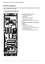
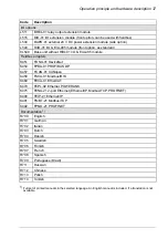
Simplified main circuit diagram
R-
L1
L2
L3
T1/U
T2/V
T3/W
R+
UDC+ UDC-
1
2
3
4
5
Rectifier. Converts alternating current and voltage to direct current and voltage.
1
DC link. DC circuit between rectifier and inverter.
2
Inverter. Converts direct current and voltage to alternating current and voltage.
3
Brake chopper. Conducts energy from the intermediate DC circuit of the drive to the brake
resistor when it is necessary and if an external brake resistor is connected to the drive. The
chopper operates when the DC link voltage exceeds a certain maximum limit. The voltage
rise is typically caused by deceleration (braking) of a motor. The user obtains and installs
the brake resistor when necessary.
4
DC connection (UDC+, UDC-).
5
Product variants
The drive has two product variants:
• Standard unit: drive with assistant control panel and RIIO-01 I/O & EIA-485 module
• Base unit: drive without control panel and without RIIO-01 I/O & EIA-485 module
(0J400+0L540) .
■
IEC and UL (NEC) product types
The ACS480 series consists of IEC product types and UL (NEC) product types. The
IEC types are designed for global use. The UL (NEC) types are specifically designed
for use in North America.
30 Operation principle and hardware description
Содержание ACS480-04-09A8-1
Страница 1: ... ABB GENERAL PURPOSE DRIVES ACS480 drives Hardware manual ...
Страница 2: ......
Страница 4: ......
Страница 14: ...14 ...
Страница 22: ...22 ...
Страница 28: ...28 ...
Страница 38: ...38 ...
Страница 44: ...44 ...
Страница 118: ...118 ...
Страница 126: ...126 ...
Страница 174: ...174 ...
Страница 176: ...Frame R0 Frame R0 front side IP20 UL open type 176 Dimension drawings ...
Страница 177: ... Frame R0 bottom rear IP20 UL open type Dimension drawings 177 ...
Страница 178: ...Frame R1 Frame R1 front side IP20 UL open type 178 Dimension drawings ...
Страница 179: ... Frame R1 bottom rear IP20 UL open type Dimension drawings 179 ...
Страница 180: ... Frame R1 front side UL Type 1 kit installed 180 Dimension drawings ...
Страница 181: ... Frame R1 bottom rear UL Type 1 kit installed Dimension drawings 181 ...
Страница 182: ...Frame R2 Frame R2 front side IP20 UL open type 182 Dimension drawings ...
Страница 183: ... Frame R2 bottom rear IP20 UL open type Dimension drawings 183 ...
Страница 184: ... Frame R2 front side UL Type 1 kit installed 184 Dimension drawings ...
Страница 185: ... Frame R2 bottom rear UL Type 1 kit installed Dimension drawings 185 ...
Страница 186: ...Frame R3 Frame R3 front side IP20 UL open type 186 Dimension drawings ...
Страница 187: ... Frame R3 bottom rear IP20 UL open type Dimension drawings 187 ...
Страница 188: ... Frame R3 front side UL Type 1 kit installed 188 Dimension drawings ...
Страница 189: ... Frame R3 bottom rear UL Type 1 kit installed Dimension drawings 189 ...
Страница 190: ...Frame R4 Frame R4 front side IP20 UL open type 190 Dimension drawings ...
Страница 191: ... Frame R4 bottom rear IP20 UL open type Dimension drawings 191 ...
Страница 192: ... Frame R4 front side UL Type 1 kit installed 192 Dimension drawings ...
Страница 193: ... Frame R4 bottom rear UL Type 1 kit installed Dimension drawings 193 ...
Страница 194: ...194 ...
Страница 221: ... Declarations of conformity The Safe torque off function 221 ...
Страница 231: ...Dimensions BIO 01 I O extension module 231 ...
Страница 232: ...232 ...
Страница 238: ...Dimensions 3AXD50000031148 rev A 238 BREL 01 relay output extension module ...