Actual signals and parameters
194
2607
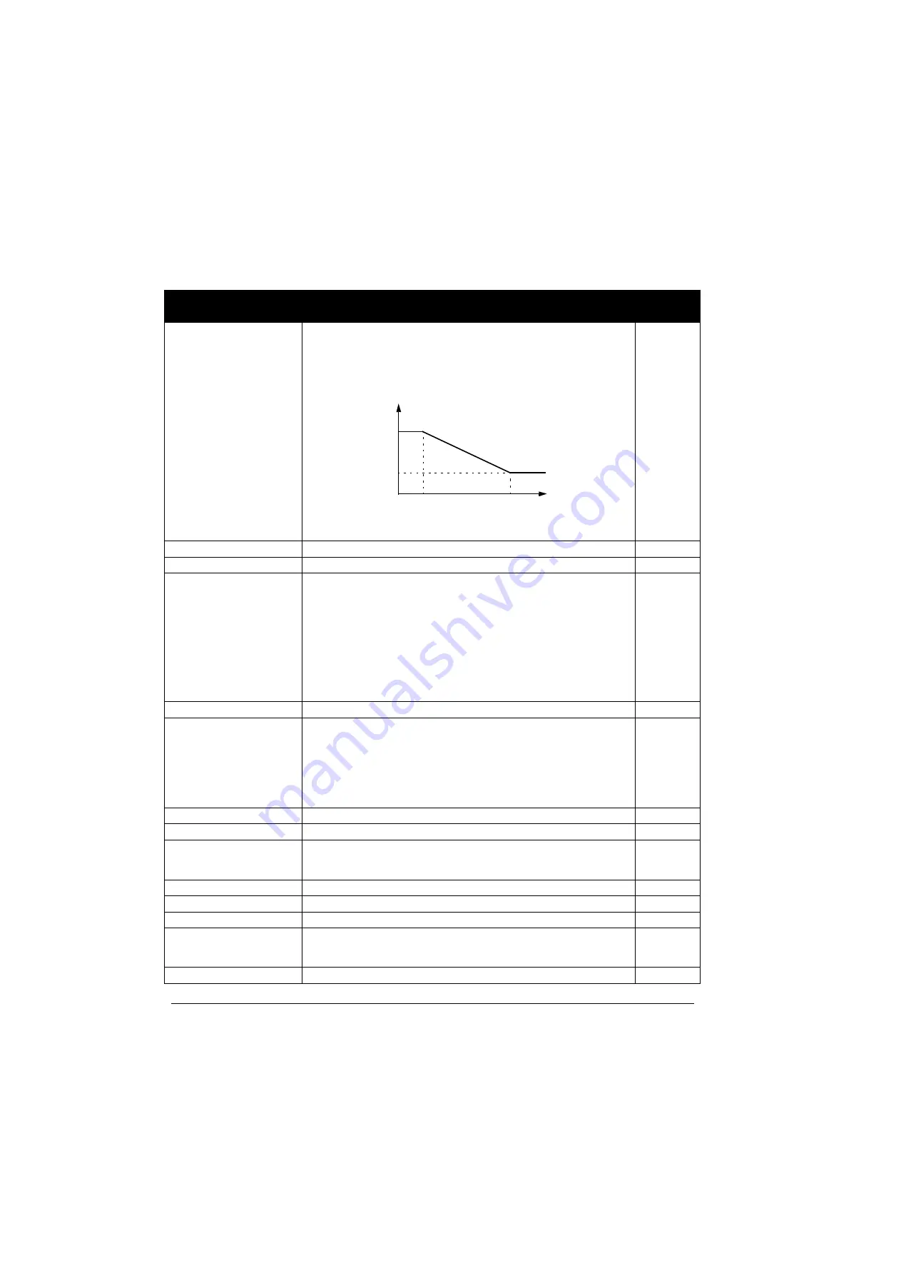
SWITCH FREQ CTRL Activates the switching frequency control. When active, the selection of
parameter
SWITCHING FREQ is limited when the drive internal
temperature increases. See the figure below. This function allows the highest
possible switching frequency at a specific operation point.
Higher switching frequency results in lower acoustic noise, but higher internal
losses.
ON
OFF
Inactive
0
ON
Active
1
2608
SLIP COMP RATIO
Defines the slip gain for the motor slip compensation control. 100% means
full slip compensation, 0% means no slip compensation. Other values can be
used if a static speed error is detected despite of the full slip compensation.
Can be used only with scalar control (i.e. when parameter
MOTOR
CTRL MODE setting is SCALAR:FREQ).
Example: 35 Hz constant speed reference is given to the drive. Despite of the
full slip compensation (SLIP COMP RATIO = 100%), a manual tachometer
measurement from the motor axis gives a speed value of 34 Hz. The static
speed error is 35 Hz - 34 Hz = 1 Hz. To compensate the error, the slip gain
should be increased.
0
0...200%
Slip gain
1 = 1%
2609
NOISE SMOOTHING
Enables the noise smoothing function. Noise smoothing distributes the
acoustic motor noise over a range of frequencies instead of a single tonal
frequency resulting in lower peak noise intensity. A random component with
an average of 0 Hz is added to the switching frequency set by parameter
SWITCHING FREQ.
Note:
Parameter has no effect if parameter
SWITCHING FREQ is set
to 16 kHz.
DISABLE
DISABLE
Disabled
0
ENABLE
Enabled
1
2610
USER DEFINED U1
Defines the first voltage point of the custom U/f curve at the frequency
defined by parameter
on page
19% of
U
N
0...120% of
U
N
V
Voltage
1 = 1 V
2611
USER DEFINED F1
Defines the first frequency point of the custom U/f curve.
10
0.0...500.0 Hz
Frequency
1 = 0.1 Hz
2612
USER DEFINED U2
Defines the second voltage point of the custom U/f curve at the frequency
defined by parameter
USER DEFINED F2. See section
on page
38% of
U
N
0...120% of
U
N
V
Voltage
1 = 1 V
Parameters – complete descriptions
Index Name/Selection
Description
Def, FbEq
80...100°C *
100...120°C *
Drive
4 kHz
16 kHz
temperature
f
sw
limit
T
* Temperature depends on the drive output frequency.
Содержание ACS350 Series
Страница 1: ...ACS350 User s Manual ACS350 Drives 0 37 22 kW 0 5 30 HP ...
Страница 4: ......
Страница 8: ...Safety 8 ...
Страница 18: ...Table of contents 18 ...
Страница 24: ...Hardware description 24 ...
Страница 44: ...Installation checklist 44 ...
Страница 56: ...Start up control with I O and ID Run 56 ...
Страница 140: ...Program features 140 ...
Страница 242: ...Actual signals and parameters 242 ...
Страница 266: ...Fieldbus control with embedded fieldbus 266 ...
Страница 284: ...Fault tracing 284 ...
Страница 288: ...Maintenance and hardware diagnostics 288 ...
Страница 309: ...Dimensions 309 Frame size R2 IP20 NEMA 1 3AFE68586658 A Frame size R2 IP20 NEMA 1 VAR EMC ...
Страница 311: ...Dimensions 311 Frame size R3 IP20 NEMA 1 3AFE68579872 B Frame size R3 IP20 NEMA 1 VAR EMC ...
Страница 312: ...Dimensions 312 Frame size R4 IP20 cabinet installation UL open Frame size R4 cabinet installation UL open 3AFE68935644 ...
Страница 313: ......


