Control panel
50
Drive selection mode
In normal use, the features available in the Drive Selection Mode are not needed;
the features are reserved for applications where several drives are connected to one
panel link. (For more information, see the
Installation and Start-up Guide for the
Panel Bus Connection Interface Module, NBCI
, [3AFY58919748 (English)].
In the Drive Selection Mode, you can:
• View the device type, drive SW loading package name and ID number
• Select the drive with which the panel communicates through the panel link
• Change the identification number of a drive connected to the panel link
• View the status of the drives connected on the panel link.
The panel enters the Drive Selection Mode when you press the
DRIVE
key.
Each on-line station must have an individual identification number (ID). By default,
the ID number of the drive is 1.
Note:
The default ID number setting of the drive should not be changed unless the
drive is to be connected to the panel link with other drives on-line.
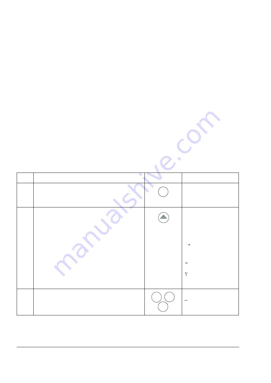
How to select a drive and change its panel link ID number
Step Action
Press
key
Display
1.
To enter the Drive Selection Mode.
ACS800
AQCCXXXX xxxxxx
ID NUMBER 1
2.
To select the next drive/view.
The ID number of the station is changed by first pressing
ENTER
(the brackets round the ID number appear) and
then adjusting the value with arrow buttons. The new value
is accepted with
ENTER
. The power of the drive must be
switched off to validate its new ID number setting.
ACS800
AQCCXXXX xxxxxx
ID NUMBER 1
The status display of all devices connected to the Panel
Link is shown after the last individual station. If all stations
do not fit on the display at once, press the double-arrow up
to view the rest of them.
Status Display Symbols:
= Drive stopped, direction
forward
= Drive running, direction
reverse
F = Drive tripped on a fault
3.
To connect to the last displayed drive and to enter another
mode, press one of the mode selection keys.
The selected mode is entered.
1 L
->
1242.0 rpm I
FREQ 45.00 Hz
CURRENT 80.00 A
POWER 75.00 %
DRIVE
1o
o
PAR
FUNC
ACT
Содержание ACS 800 Series
Страница 1: ...ACS800 Firmware Manual Crane Control Program N697 ...
Страница 4: ......
Страница 26: ...Start up and control through the I O interface 26 ...
Страница 36: ...Quick start up guide 36 ...
Страница 52: ...Control panel 52 ...
Страница 105: ...Program features 105 Figure Control diagram for Shaft synchronisation executed in 20 ms ...
Страница 126: ...Program features 126 The figures below show speed limits according to different load conditions ...
Страница 128: ...Program features 128 ...
Страница 150: ...Application macros control location EXT1 EXT2 150 ...
Страница 228: ...Actual signals and parameters 228 ...
Страница 299: ...Adaptive Programming examples for crane control 299 ...
Страница 305: ...Adaptive Programming examples for crane control 305 ...
Страница 312: ...Adaptive Programming examples for crane control 312 The following figures show the previous example enlarged ...
Страница 314: ...Adaptive Programming examples for crane control 314 The following figures show the previous example enlarged ...
Страница 318: ...Analogue Extension Module 318 ...
Страница 332: ...Additional data actual signals and parameters 332 ...
Страница 333: ...DriveWindow 333 DriveWindow DriveWindow connected to the ACS800 RMIO RDCO board and channel CH3 ...
Страница 334: ...DriveWindow 334 ...
Страница 335: ...Control block diagrams 335 Control block diagrams ...
Страница 336: ...Control block diagrams 336 ...
Страница 337: ...Control block diagrams 337 ...
Страница 338: ...Control block diagrams 338 ...
Страница 340: ...www abb com drives www abb com drivespartners Contact us 3AFE68775230 Rev E EN 2012 09 25 ...


